
789D Off-Highway Truck
ENGINE AND SUPPORT SYSTEM

INTRODUCTION
There are three engine configurations available on the 789D truck. All engines are equipped with the Mechanical Electronic Unit Injection (MEUI) system.
The 3516B engine is Tier 1 compliant and will maintain the current 789C rating of 1415 kW (1900 hp). The 3516B intake air is cooled by a Separate Circuit AfterCooler (SCAC), the same as the 3516B in the 789C.
The higher horsepower 3516C is rated at 1566 kW (2100 hp) and will be available in an emissions compliant version (Tier 2) and an optimal fuel efficiency version. The intake manifold air is cooled with an Air to Air AfterCooler (ATAAC). The aftercooler pump that is used on the 3516B is used as the auxiliary coolant pump on the 3516C, which circulates coolant through the front brake oil cooler.
The updated 3516B and the 3516C engines have improvements over the previous 3516B engine. Some of the improvements include an A4:E4 Engine Electronic Control Module (ECM) and additional switch and sensor inputs to the Engine ECM. Adding additional inputs allows the ECM to control the engine more precisely.
NOTE: The 3516B and 3516C engines are similar and differences will be noted where necessary.

Identify components and service points on right side of engine
The main components on the right side of the engine are:* Alternator (1) .
* Water pump (2) .
* Oil pump (3) .
* Brake oil coolers (4) .
* Crankcase vent filter (5).
* Engine oil cooler (6) .
* Priming pump fuel filter (7).
* Turbochargers (8) .

Identify components and service points on left side of engine
The main components on the left side of the engine are:* Air starter (1) .
* Engine ECM (2) .
* Engine oil dipstick (3).
* Engine oil filters (4).
* Engine oil fill tube (5).
* Engine oil ecology drain (6).
* Air compressor (7) .
* Secondary fuel filters (8).
* Crankcase vent filters (9).

Identify engine electronic control system input and output components.
ENGINE ELECTRONIC CONTROLSYSTEM
Shown is the electronic control system engine diagram for the 3516B and 3516C engines used in the 789D truck. Fuel injection is controlled by the A4:E4 Engine ECM (1).
Many electronic signals are sent to the Engine ECM by sensors and switches. The Engine ECM analyzes these signals and determines when and for how long to energize the injector solenoids. When the injector solenoids are energized determines the timing of the engine. How long the solenoids are energized determines the engine speed.
The following sensors have been added to the 3516B and 3516C engines:
* Engine Speed Sensor (crank) (21)
* Coolant Pressure Sensor (28)
* Fuel Pressure Sensor (pre-filter) (29)
* Fuel Pressure Sensor (post-filter) (30)
NOTE: The Intake Manifold Air Temperature Sensor (19) and Front Aftercooler Temperature Sensor (10) are new on the 3516B engine.
The Engine ECM also regulates other systems by energizing solenoids or relays. Some of the other systems and functions controlled by the ECM are:
* Ether injection (now automatically controlled by the Engine ECM; • manual ether switch has been eliminated)
* Optional variable speed fan •
* Oil Renewal System •
* Fuel priming •
* Cool engine elevated idle •
* Cold cylinder cutout (reduces unburned fuel after start-up and during • extended idling in cold weather) Engine starting (Engine ECM provides signals to the Transmission/ •
* Chassis ECM and Transmission/Chassis ECM energizes the starter relay)

Identify Engine ECM and atmospheric pressure sensor.
Fuel injection and system monitoring are controlled by the A4:E4 Engine ECM (1), which is located on the left side of the engine. The Engine ECM is equipped with a 120-pin connector (J2) and a 70-pin connector (J1).The Engine ECM responds to engine inputs by sending a signal to the appropriate output component to initiate an action. For example, the Engine ECM receives a high coolant temperature signal. The Engine ECM interprets the input signal, evaluates the current operating status, and derates the fuel supply under load.
The Engine ECM receives three different types of input signals:
* Switch input : Provides the signal line to battery, ground, or open.
* PWMinput : Provides the signal line with a rectangular wave of a specific frequency and a varying positive duty cycle.
* Speed signal : Provides the signal line with either a repeating, fixed voltage level pattern signal, or a sine wave of varying level and frequency.
The Engine ECM has three types of output drivers:
* ON/OFFdriver : Provides the output device with a signal level of +Battery voltage (ON) or less than one Volt (OFF).
* PWM driver : Provides the output device with a rectangular wave of fixed frequency and a varying positive duty cycle.
* Controlled current output driver : The ECM will energize the solenoid with pull-up current for a specific duration and then decrease the level to hold-in current for a specific duration of the on time. The initial higher amperage gives the actuator rapid response and the decreased level is sufficient to hold the solenoid in the correct position. An added benefit is an increase in the life of the solenoid.
The Engine ECM has built-in diagnostic capabilities. As the Engine ECM detects fault conditions in the power train system, the ECM logs events in memory and diagnostic codes for troubleshooting and displays them through Cat ET.
The atmospheric pressure sensor (2) is located in the control panel next to the Engine ECM. The function of the atmospheric pressure sensor is to supply information relative to high altitude back to the Engine ECM along with calculated gauge pressure for all the pressure sensors to the ECM. Losing the signal from the atmospheric pressure sensor will initiate a 10% derate and the parameter will be set to a default value that is stored in the ECM.
Normally, at 0 rpm and 2 seconds after the engine starts, the Engine ECM reads each pressure sensor to ensure the pressure is within tolerance of a specified value. If the value is within tolerance, the Engine ECM compares the value of the pressure sensors with the atmospheric sensor and assigns a specific offset value to each sensor for calibration.
NOTE: The signal from the atmospheric pressure sensor is used by the Engine ECM to calculate a number of pressure measurements in most electronic engines. The signal from the atmospheric pressure sensor is compared to the signal from the other engine pressure sensors to calibrate the pressure sensors. When the Engine ECM is powered up, the ECM uses the signal from the atmospheric pressure sensor as a reference point for calibration of the other pressure sensors on the engine.

Identify speed/timing sensors
The crankshaft speed/timing sensor (1) is new on the 3516B and 3516C engines. The crankshaft sensor is located at the right rear of the engine. The crankshaft speed/timing sensor sends a fixed voltage level signal to the Engine ECM indicating the engine speed, direction, and timing. The crankshaft sensor is the primary speed/ timing sensor reporting to the Engine ECM to determine engine speed and crankshaft position. The speed sensor detects the reference for engine speed and timing from a unique pattern on the respective gear. Normally, the crankshaft speed/timing sensor identifies the timing during starting and determines when the No. 1 cylinder is at the top of the stroke. Once the timing is established, the crankshaft timing sensor is used to relay the engine speed and the camshaft timing sensor signal is ignored.In case of a crankshaft speed/timing sensor failure, the Engine ECM follows the following process:
* A crankshaft sensor diagnostic code is logged •
* The Engine ECM switches to the camshaft speed/timing sensor (2) •
* The Engine ECM uses the stored rotation as the engine rotation if the • sensor fails during a pattern lock
The crankshaft speed/timing sensor serves four functions:
* Engine speed measurement .
* Engine timing measurement .
* TC location and cylinder number identification .
* Reverse rotation protection .
The camshaft speed/timing sensor is located on the left side of the engine at the rear and indicates camshaft speed. The camshaft speed/timing sensor is used to synchronize fuel delivery with the engine cycle and provides a backup if the crankshaft speed/timing sensor fails. If the crankshaft speed/timing sensor fails, the Engine ECM will use the camshaft speed/timing sensor to keep the engine running, but the fuel delivery may be less accurate. The crankshaft sensor and the camshaft sensor adjustment is preset so no adjustment is necessary.

Identify throttle position sensor.
The throttle position sensor (arrow) provides the desired throttle position to the Engine ECM. If the Engine ECM detects a fault in the throttle position sensor, the throttle back-up switch on the dash panel can be used to increase the engine speed to 1300 rpm. The throttle position sensor receives a regulated 8.0 ± 0.5 volts from the Engine ECM. The throttle position sensor output signal is a Pulse Width Modulated (PWM) signal that varies with throttle position and is expressed as a percentage between 0 and 100%.
Identify MEUI injector solenoid
Shown is the top of a cylinder head with the valve cover removed. The most important output from the Engine ECM is the Mechanical Electronic Unit Injection (MEUI) injector solenoid (arrow). One injector is located in each cylinder head. The engine control analyzes all of the inputs and sends a signal to the injector solenoid to control engine timing and speed.Engine timing is determined by controlling the start and end time that the injector solenoid is energized. Engine speed is determined by controlling the duration that the injector solenoid is energized.
The injectors are calibrated during manufacturing for precise injection timing and fuel discharge. After the calibration, a four-digit “E-trim” code number is etched on the injector tappet surface. The E-trim code identifies the injector’s performance range.
When the injectors are installed into an engine, the trim code number of each injector is entered into the Engine ECM using Cat ET. The software uses the trim code to compensate for the manufacturing variations in the injectors and allows each injector to perform as a nominal injector. When an injector is serviced, the new injector’s trim code should be programmed into the Engine ECM. If the new trim code is not entered, the previous injector’s characteristics are used. The engine will not be harmed if the new code is not entered, but the engine will not provide peak performance.

Identify crankcase pressure sensor
The crankcase pressure sensor (arrow) is located on the right side of the engine above the engine oil cooler. The crankcase pressure sensor provides an input signal to the Engine ECM. The ECM provides the signal to the VIMS, which informs the operator of the crankcase pressure. High crankcase pressure may be caused by worn piston rings or cylinder liners. If crankcase pressure exceeds 3.6 kPa (.5 psi) or 14.4 inches of water, a high crankcase pressure event will be logged. No factory password is required to clear this event.
Identify front engine mount and pre-lubrication pump
The engine oil pre-lubrication attachment is controlled by the Engine ECM and Transmission/Chassis ECM. The Engine ECM energizes the pre-lubrication pump relay located behind the cab. The relay behind the cab then energizes the pre-lube relay (not visible) mounted to the rear of the front engine mount (1). The Engine ECM signals the Transmission/Chassis ECM to crank the engine when:* Engine oil pressure is 3 kPa (.4 psi) or higher.
* The pre-lubrication pump (2) has run for 17 seconds. (If the system • times out after 17 seconds, a pre-lubrication time out fault is logged in the Engine ECM.)
* The engine has been running in the last two minutes.
* Coolant temperature is above 50°C (122°F).
The engine oil pre-lubrication system can be bypassed to allow quick starts. To override the pre-lubrication system, turn the key start switch to the CRANK position for a minimum of two seconds. The Transmission/Chassis ECM will begin the pre-lube cycle. While the pre-lube cycle is active, turn the key start switch to the OFF position. Within 10 seconds, turn the key start switch back to the CRANK position. The Transmission/Chassis ECM will energize the starter relay.
If the engine oil pre-lubrication system is bypassed using the above procedure, the Engine ECM will log a pre-lube override event that requires a factory password to clear. NOTE: Cat ET can enable or disable the pre-lubrication feature in the Engine ECM.

Identify components at front of engine
If the engine is equipped with a variable speed fan, the Engine ECM regulates the fan speed. Fan speed varies according to the temperature of the engine. The ECM sends a signal to the variable speed fan control solenoid valve (1), and engine oil pressure engages the fan clutch (2) as needed to change the speed of the fan.The coolant temperature sensor (3) is located in the jacket water temperature regulator (thermostat) housing. The ECM uses the coolant temperature sensor information as the main parameter to control the fan speed. The air conditioner status switch and brake cooling oil temperature sensors are also used as inputs to determine the required fan speed. A speed sensor (not shown) is located behind the fan pulley and informs the ECM of the current fan speed.
The air conditioner status switch signals the Engine ECM when the air conditioner system is ON. When the air conditioner system is ON, the ECM sets the variable speed fan at MAXIMUM rpm. Disconnecting the air conditioning status switch will signal the ECM to set the fan speed at MAXIMUM rpm.
The variable speed fan feature can be turned off using Cat ET. Turning off the variable speed fan feature will set the fan speed at MAXIMUM rpm.

Identify engine oil renewal solenoid valve.
The optional Oil Renewal System (ORS) components are located on the right side of the engine. Engine oil flows from the engine block to the engine oil renewal solenoid valve (arrow). When the solenoid is energized and de-energized, a small amount of oil flows from the engine oil renewal solenoid valve into the fuel line that returns to the fuel tank. The engine oil mixes with the fuel in the tank and flows with the fuel to the MEUI injectors to be burned.If the machine is equipped with the engine oil renewal system, the engine oil filters, the engine oil renewal system filter, the primary fuel filter, and the secondary fuel filters must all be changed at 500 hour intervals. The engine oil should be changed at least once per year or 4000 service meter hours. Engine oil samples must be taken regularly to ensure that the soot level of the engine oil is in a safe operating range.
The Engine ECM regulates the amount of oil that is injected by the engine oil renewal solenoid valve. Several parameters must be met before the ECM will allow the injection of oil through the engine oil renewal system. The parameters that must be met are:
* Fuel position is greater than 10..
* Engine rpm is between 1100 and 1850 rpm..
* Jacket water temperature is between 63°C (145°F) and 107°C (225°F).
* Fuel filter differential pressure is less than 140 kPa (20 psi).
* Fuel level is greater than 10%.
* Engine oil level switches are sending a valid signal to the Engine ECM.
* Engine has been running more than five minutes.
The engine oil renewal system can be turned ON or OFF and the amount of oil injected can also be adjusted with Cat ET. The factory setting shown in the service tool is “0” and is equivalent to a 0.5% oil to fuel ratio. The ratio can be changed with the service tool from minus 50 (-50) to plus 50 (+50), which is equivalent to 0.25% to 0.75% oil to fuel ratios.

Explain operation of oil renewal solenoid valve
Shown is a sectional view of the engine oil renewal solenoid valve. When the Engine ECM determines that oil can be injected into the fuel return line, a Pulse Width Modulated (PWM) duty cycle signal is sent to the oil renewal solenoid. The solenoid is turned ON for 1.25 seconds and turned OFF for 1.25 seconds for a total cycle time of 2.5 seconds. How many times the solenoid is turned ON and OFF will determine the volume of oil that is injected. Oil from the engine oil gallery (1) is injected when the solenoid is turned ON and oil is also injected when the solenoid is turned OFF.When the solenoid is turned ON, engine oil flows to the left side of the piston (2) and pushes the piston to the right. The volume of oil that is trapped between the right side of the piston and the check ball compresses the spring and opens the passage to the fuel return line (3). When the solenoid is turned OFF, engine oil flows to the right side of the piston and pushes the piston to the left. The volume of oil that is trapped between the left side of the piston and the check ball compresses the spring and opens the passage to the fuel return line. The volume of delivery is equal to 3.04 ml/cycle (0.1 oz./cycle).

Identify components of jacket water cooling system, left side of engine.
COOLINGSYSTEMThis image shows the main components in the jacket water cooling system:
* Shunt tank (1)
* Radiator (2)
* Thermostat housing (3)
* Coolant pump (4)
* Transmission oil cooler (5)
* Rear brake oil coolers (6)
* Engine oil cooler (7)
* Front brake oil cooler (8)
The 3516C jacket water cooling system is similar to the 3516B jacket water cooling system. However, the 3516C uses an ATAAC core rather that an aftercooler to cool the intake air. The aftercooler pump that is used on the 3516B engine functions as an auxiliary pump on the 3516C engine, which sends coolant to the front brake oil cooler.
The cooling system in the updated 3516B engine is divided into two systems similar to the previous 3516B engine cooling system. The two systems are the jacket water cooling system and the aftercooler cooling system. The only connection between these two systems is a small hole in the separator plate in the shunt tank. The small hole in the shunt tank prevents a reduction of coolant from either of the two systems if leakage occurs in one of the separator plates in the radiator top or bottom tank. When servicing the cooling systems, be sure to drain and fill both systems separately.


Identify shunt tanks and components
The coolant level is checked at the shunt tank. The shunt tank provides a positive pressure at the coolant pump inlets to prevent cavitation during high flow conditions. The top image shows the single shunt tank (1) for the jacket water cooling system on the 3516C engine. The bottom image shows the shunt tank (2) for the jacket water cooling system and the shunt tank (3) for the aftercooler cooling system on the 3516B engine.Use the gauges (4) on top of the shunt tank to check the coolant level.
Coolant level switches (5) are located on the side of each shunt tank to monitor the coolant level. The coolant level switches provide input signals to the VIMS, which informs the operator of the engine coolant levels.
The jacket water and the aftercooler cooling systems each have their own relief valve (6). If a cooling system overheats or if coolant is leaking from a relief valve, clean or replace the relief valve.
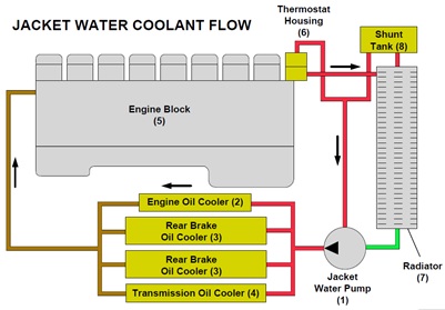
Explain operation of jacket water cooling circuit
Shown is the jacket water cooling circuit. Coolant flows from the jacket waterpump (1) through the engine oil cooler (2), the rear brake oil coolers (3), and the transmission oil cooler (4) to the engine block (5). Coolant flows through the engine block and the cylinder heads. From the cylinder heads the coolant flows to the thermostats located in the thermostat housing (6), and either flows directly to the water pump through the bypass tube, or to the radiator (7), depending on the temperature of the coolant. The shunt tank (8) increases the cooling capacity and provides a positive pressure at the coolant pump inlet to prevent cavitation during high flow conditions.


Identify cooling system components
The coolant temperature sensor (1) is located in the temperature regulator housing. The coolant temperature sensor sends signals to the Engine ECM indicating engine coolant outlet temperature. The ECM also uses the coolant temperature sensor information as the main parameter to control the fan speed.The coolant pressure sensor (2) is located in the water pump housing on the right side of the engine. The coolant pressure sensor sends signals to the Engine ECM
indicating engine coolant inlet pressure. The coolant pressure sensor is a new sensor on the 3516 engines. Also visible is the engine coolant S•O•S port (3).

Explain 3516B aftercooler cooling system coolant flow
3516B aftercooler Cooling System Shown is the 3516B aftercooler cooling circuit. Coolant flows from the aftercooler water pump (1) through the aftercooler (2) and front brake oil cooler (3) to the aftercooler section of the radiator (4). The aftercooler cooling circuit does not have temperature regulators (thermostats) in the circuit. The shunt tank (5) increases the cooling capacity and provides a positive pressure at the aftercooler water pump inlet to prevent cavitation during high flow conditions. The aftercooler water pump also sends coolant to the air compressor (6).
Identify 3516B aftercooler cooling system components
This image shows the main components in the 3516B aftercooler cooling system:* Aftercooler water pump (1)
* Radiator (2)
* Aftercooler (3)
* Front brake oil cooler (4)
* Air compressor (5)

Identify 3516C auxiliary cooling circuit components
3516C Auxiliary Cooling Circuit The 3516C engine does not have a water cooled aftercooler since the intake air is cooled by an air to air aftercooler (5). An auxiliary water pump (1) provides coolant to the front brake oil cooler (2) and the air compressor (3).
From the front brake oil cooler the coolant is returned to the engine. Coolant from the engine flows to the radiator if the thermostat is open, or back to the auxiliary coolant pump through the return hose (4) if the thermostat is closed.

Explain oil flow through engine oil system
LUBRICATIONSYSTEMThe engine oil pump (1) draws oil from the oil pan through a screen (2).
The engine also has a scavenge pump (3) at the rear of the engine to transfer oil from the rear of the oil pan to the main sump.
Oil flows from the pump through an engine oil cooler bypass valve (4) to the engine oil cooler (5). The bypass valve for the engine oil cooler permits oil to flow to the
system during cold starts when the oil is thick or if the cooler is plugged. Oil flows from the engine oil cooler to the oil filters (6). The oil flows through the filters and enters the engine cylinder block to clean, cool, and lubricate the internal components and the turbochargers.
Some trucks are equipped with the optional Oil Renewal System (ORS). Engine oil flows from the engine block to an engine oil renewal system manifold. The ORS solenoid (7) allows a small amount of oil to flow from the engine oil renewal system manifold into the return side of the fuel pressure regulator. The engine oil returns to the fuel tank (8) with the return fuel

Identify components on right side of engine
The engine oil pump (1) is located behind the jacket water pump (2) on the right side of the engine. The oil pump draws oil from the oil pan through a screen. A relief valve for the lubrication system is located on the pump.The engine also has a scavenge pump at the rear of the engine to transfer oil from the rear of the oil pan to the main sump. Oil flows from the pump through an engine oil cooler bypass valve to the engine oil cooler (3). The bypass valve for the engine oil cooler permits oil flow to the system during cold starts when the oil is thick or if the cooler is plugged.

Identify components on left side of engine
Oil flows from the engine oil cooler to the oil filters (1) on the left side of the engine. The oil flows through the filters and enters the engine cylinder block to clean, cool, and lubricate the internal components and the turbochargers.Engine oil is added at the fill tube (2) and checked with the dipstick (3). A bypass valve for each filter is located in each oil filter base. Engine oil samples can be taken at the S•O•S port (4).
The engine has two oil pressure sensors. One sensor is located on each end of the oil filter base. The pre-filter oil pressure sensor (5) measures engine oil pressure before the filters. The post-filter oil pressure sensor (not visible, on the front of the filter base) measures oil pressure after the filters. The sensors send input signals to the Engine ECM. The ECM provides the input signal to the VIMS, which informs the operator of the engine oil pressure. Used together, the two engine oil pressure sensors inform the operator if the engine oil filters are restricted.
If the engine oil pressure is less than 44 kPa (6.4 psi) at LOW IDLE to less than 250 kPa (36 psi) at HIGH IDLE, the Engine ECM will log an event that requires a factory password to clear.
If the oil filter restriction exceeds 70 kPa (10 psi), a low oil filter restriction event will be logged. No factory password is required to clear this event. If the oil filter restriction exceeds 200 kPa (28 psi), a high oil filter restriction event will be logged. A factory password is required to clear this event.
Also visible in this image is the oil level sensor (6) and the engine coolant S•O•S port (7).

Explain engine fuel flow
FUELSYSTEMFuel is drawn from the fuel tank (1) through an optional fuel heater (2), and through the primary fuel filter (3) by the fuel transfer pump (4). A fuel/water separator can be installed on the primary fuel filter.
The fuel transfer pump sends fuel through the secondary fuel filters (5) to the fuel injectors in the cylinder heads (6). Unused fuel returns from the injectors and flows through the fuel pressure regulator (7). As the pressure builds above the regulator pressure, the regulator opens and flow is directed back to the fuel tank.
The 3516 engines now have two fuel pressure sensors that replace the fuel pressure differential switch. The pre-filter fuel pressure sensor (8) measures fuel pressure before the filters. The pre-filter fuel pressure sensor (9) measures oil pressure after the filters. The sensors send input signals to the Engine ECM (10). The ECM provides the input signal to the VIMS, which informs the operator of the fuel pressure. Used together, the two fuel pressure sensors inform the operator if the secondary fuel filters are restricted.
The electric fuel priming pump and filter (11) and the fuel priming pump switch (12) replace the manual fuel priming pump on the previous 3516B engines. When the fuel priming pump switch is activated, current is sent to the fuel priming pump and the pump draws fuel from the tank and primary fuel filter. The fuel is sent to the fuel transfer pump where it is blocked. The fuel also flows through a check valve to the secondary fuel filters.
NOTE: If the fuel system requires priming, it may be necessary to block the fuel return line during priming in order to force the fuel into the injectors.

Identify components on left side of truck
The fuel tank is located on the left side of the truck. The fuel tank now has three sight gauges (1) for a more accurate fuel level reading from outside the truck. The fuel fast fill port (2) is also located on the left side of the tank.The primary fuel filter (not visible) is mounted to the inboard side of the tank.
Located at the rear of the fuel tank are the following fast fill ports:
* Engine oil (3)
* Transmission oil (4)
* Hydraulic oil (5)
* Steering oil (6)
* Engine coolant (7)

Identify components inside fuel tank
Baffles (1) have been added to the fuel tank to decrease fuel slosh.A fuel level sensor (2) is also located in the fuel tank. The fuel level sensor emits an ultrasonic signal that bounces off a metal disk on the bottom of a float. The time
it takes for the ultrasonic signal to return is converted to a Pulse Width Modulated (PWM) signal. The PWM signal changes as the fuel level changes. The fuel level sensor provides the input signals to the VIMS, which informs the operator of the fuel level. A category level 1 warning (FUEL LVL LO) is shown on the VIMS display if the fuel level is less than 15%. A category level 2 warning (FUEL LVL LO ADD FUEL NOW) is shown on the VIMS display if the fuel level is less than 10%.

Identify transfer pump and bypass valve
Fuel flows from the transfer pump (1) to the secondary fuel filters located on the left side of the engine. The fuel transfer pump contains a bypass valve (2) to protect the fuel system components from excessive pressure. The bypass valve setting is 860 kPa (125 psi), which is higher than the setting of the fuel pressure regulator.

Identify components on left side of engine
The secondary fuel filters (1) and the electric fuel priming pump switch (2) are located above the engine oil filters on the left side of the engine. The fuel priming pump switch activates the fuel priming pump (3), which is used to fill the filters after they are changed. The fuel priming pump and priming filter (4) are located on the right side of the engine. A 10 amp circuit breaker (5) protects the fuel priming pump circuit.
The pre-filter fuel pressure sensor (6) and post-filter fuel pressure sensor (7) send input signals to the Engine ECM. The ECM provides the input signal to the VIMS, which informs the operator of the fuel pressure. Used together, the two fuel pressure sensors inform the operator if the secondary fuel filters are restricted.
If fuel filter restriction exceeds 138 kPa (20 psi), a fuel filter restriction event is logged. No factory password is required to clear this event.
Fuel flows from the fuel filter base through the fuel injectors, the fuel pressure regulator, and then returns to the fuel tank. The injectors receive 4 1/2 times the amount of fuel needed for injection. The extra fuel is used for cooling.

Identify fuel pressure regulator
Fuel flows from the secondary fuel filters to the fuel injectors. Return fuel from the injectors flows through the fuel pressure regulator (arrow) before returning to the fuel tank. The fuel pressure is controlled by the fuel pressure regulator. The fuel pressure should between 380 kPa (55 psi) and 621 kPa (90 psi).
Explain operation of 3516C air induction and exhaust system
This illustration is a schematic showing the air flow from the air filters to the mufflers on the 3516C engine.NOTE: The air flow on the 3516B engine is similar, except the compressed air from the turbochargers flows to the water cooled aftercooler rather than to the
Air to Air AfterCooler as on the 3516C engine. The turbochargers are driven by the exhaust (1) from the cylinders, which enters the turbine side of the turbochargers (2). The exhaust gas flows through the turbochargers, the exhaust piping, and the mufflers (3). The clean air from the air filters (4) enters the compressor side of the turbochargers. The compressed air from the turbochargers flows to the aftercooler. This illustration shows the ATAAC cores on the 3516C engine. The aftercooler core is water cooled on the 3516B engine. After the air is cooled by the aftercoolers, the air flows through the intake manifold (5) to the cylinders and combines with the fuel for combustion.

Identify air filters and dust valves
The engine receives clean air through the air filters (1) located on the front of the truck.Check the dust valves (2) for plugging. If necessary, disconnect the clamp and open the cover for additional cleaning. The dust valve is OPEN when the engine is OFF and closes when the engine is running. The dust valve must be flexible and close when the engine is running or the precleaner will not function properly and the air filters will have a shortened life. Replace the rubber dust valve if it becomes hard and not flexible.
The VIMS will also provide the operator with an air filter restriction warning when the filter restriction is approximately 6.2 kPa (25 in. of water). Black exhaust smoke is also an indication of air filter restriction. Two filter elements are installed in the filter housings. The large element is the primary element and the small element is the secondary element.


Identify turbocharger air inlet pressure sensors
The turbocharger air inlet pressure sensors (arrows) are mounted in the air tubesbetween the air filters and the turbochargers. The signal from the pressure sensors is monitored by the Engine ECM. Based on the sensor signals, the Engine ECM can determine when the air filters have become restricted with dirt and contaminants. The Engine ECM will send an alert message to the monitoring system when the air filters require servicing. Engine derate can occur if the engine air filters are restricted.

Identify intake manifold temperature sensor
The intake manifold temperature sensor (arrow) is located at the rear of the engine in the intake manifold.The intake air temperature sensor is new to the 3516B engine. The intake air temperature sensor produces an analog signal that is monitored by the Engine
ECM. The ECM monitors intake air temperature for derating the engine at high temperatures, for engine shutdown at high temperatures, and for signaling the monitoring system in the event of a problem. NOTE: If a high temperature event is severe enough, the monitoring system will issue a Level 3 warning. The operator must park the machine as soon as possible. When the Engine ECM determines that the ground speed is zero and the transmission is in PARK, the engine will automatically shut down.

Identify intake manifold air pressure sensor
The intake manifold air pressure sensor (arrow) is located in the Y-pipe monitoring the air pressure from the ATAAC. The intake manifold pressure sensor sends an input signal to the Engine ECM. The Engine ECM compares the value of the intake manifold pressure sensor with the value of the atmospheric pressure sensor and calculates boost pressure.

Identify exhaust temperature sensors
The left exhaust temperature sensor (1) and the right exhaust temperature sensor (2) are located in the exhaust manifold on both sides of the engine. The exhaust temperature sensors send a signal to the Engine ECM indicating exhaust temperature.When the engine runs at low idle, the temperature of an exhaust manifold port can indicate the condition of a fuel injection nozzle. A low temperature indicates that no fuel is flowing to the cylinder. An inoperative fuel injection nozzle or a problem with
the fuel injection pump could cause this low temperature. A very high temperature can indicate that too much fuel is flowing to the cylinder. A malfunctioning fuel injection nozzle, plugged air filters, or a restriction in the turbochargers or the muffler could cause this very high temperature.
Engine and Support Systems Component Identification
Instructions: Use the worksheet as a checklist while identifying the components on the 789D Off-Highway Truck.
Locate the following components on the 3516 engine.
______ Air starter ______ Alternator
______ Water pump ______ Oil pump
______ Engine ECM ______ Engine oil dipstick
______ Engine oil filters ______ Brake oil coolers
______ Crankcase vent filter ______ Engine oil cooler
______ Engine oil fill tube ______ Engine oil ecology drain
______ Air compressor ______ Secondary fuel filters
______ Priming pump fuel filter ______ Turbochargers
______ Crankcase vent filters

Engine and Support Systems Component Identification (continued)
Instructions: Identify the numbered components in the above illustration.
1. Fuel tank
2. Primary fuel fi lter
3. Secondary fuel fi lter
4. Fuel pressure regulator
5. Fuel pressure sensor ( post filter)
6. Fuel priming pump and filter
7. Fuel heater (optional)
8. Fuel transfer pump
9. Cyli nder head
10. Fuel pressure sensor (pre filter)
11. Eengine ECM
12. Fuel priming pump switch

LAB 1: Engine and Support Systems Component Identification (continued)
Instructions: Identify the numbered components in the above illustration.
1. Shunt tank.
2. Radiator.
3. Thermostat housing
4. Coolant pump
5. Transmission oil cooler
6. Rear brake oil cooler
7. Engine oil cooler
8. Front brake oil cooler

LAB 1: Engine and Support Systems Component Identification (continued)
Instructions: Identify the numbered components in the above illustration.

789D Off-Highway Trucks Engine and Support Systems Post-Assessment
Instructions: Select the correct answer(s) for each question.
1. Which sensor input to the Engine ECM is used to determine engine speed and crankshaft position?
a. [Crankshaft speed/timing sensor]a.
b. Flywheel speed sensorb.
c. Primary engine speed/timing sensorc.
d. Timing gear position sensord.
2. The Engine ECM uses coolant temperature sensor information as the main parameter to control the -------
a. coolent level requirementsa.
b. jacket water pumpb.
c. [fan speed]c.
d. aftercooler pumpd.
3. How many fuel pressure sensors are located on the 3516 engine?
a. 1.
b. 2.
c. 3.
d. 4.
4. What is the purpose of the fuel transfer pump?
a. Provides fuel flow to the ARD fuel manifolda.
b. Transfers fuel from the tank to the primary fuel filterb.
c. Provides fuel to cool the Engine ECMc.
d. Provides fuel to the secondary fuel filter.
5. The Engine ECM monitors the intake air temperature sensor for ______ (select all that apply)
a. derating the engine at high temperatures.
b. engine shutdown at high temperatures.
c. signaling the monitoring system in the event of a problem
d. determining exhaust temperature
6. Which of the following sensors is new to the 3516B and 3516C engines?
a. Coolant pressure sensor.
b. Fuel differential pressure sensor.
c. Fuel temperature sensor.
d. Camshaft speed/timing sensor.
ENGINE 3516 B ON HAULTRUCK 789D
 Reviewed by heri
on
10:09 PM
Rating:
Reviewed by heri
on
10:09 PM
Rating:
Reviewed by heri
on
10:09 PM
Rating:


No comments: