

BRAKE AND FAN SYSTEM
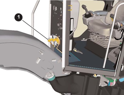
Service Brake SystemThe brake and fan pump (1) is located on the left front side of the transmission case. The brake and fan pump is a variable displacement piston pump with a pressure and flow compensator valve. The piston pump provides oil flow for the brake and fan hydraulic systems.

The priority valve (1) directs most of the oil to the brake system until the brake accumulators are fully charged. Once the accumulators have been charged, all of the oil flow is then sent to the fan motor. The fan speed solenoid (2) controls the amount of signal oil that travels from the fan circuit to the brake and fan pump. The cut-in valve (3) and cut-out valve (4) control the
cut-in and cut-out pressure for the brake system. The pressure tap (5) is used for testing the pressure in the brake and fan system. The Transmission/Chassis ECM uses the pressure sensor (6) to monitor the accumulator charge oil pressure. The relief valve (7) limits the maximum pressure in the brake and fan system.


Service Brake Valve Not Activated
The service brake valve has two individual brake ports. Also, the brake valve has two individual spools which control the flow of oil to the individual brake ports. The upper brake port is for the right service brakes and the lower brake port is for the left service brakes. With the service brake valve, the pressure at the upper brake port is 207 kPa (30 psi) higher than the pressure at the lower brake port. Also, the spring force will be proportional to the plunger movement.The brake control valve is equipped with a check valve. The check valve prevents spikes in the tank port from entering the cavity with the plungers springs and acting on the the plunger and eventually transferring to the brake pedal.
The brake control valve is also equipped with shims that are between the ball retainer and the plunger spring. These shims are used to adjust the maximum pressure that is directed to the service brakes.

Service Brake Valve – Activated
In order to initiate the operation of the service brake valve, the operator depresses the brake pedal (not shown). The brake pedal contacts the plunger. The plunger is pushed in the downward direction against the plunger and return springs. The plunger spring puts a downward force on the ball retainer, the ball, the upper spool down, and the lower spool. The right brake port will be blocked from the upper tank port. The right brake port will then be open to flow from the system pressure port (from the right brake accumulator). Also, the system oil flows through the orifice and the upper spool passage into the cavity between the upper spool and the lower spool. The oil pressure on the bottom area of the upper piston puts an upward force on the upper spool pushing the spool against the plunger spring.The upper spool moves the lower spool downward compressing the lower return spring. The left brake port will then be open to flow from the system pressure port (from the left brake accumulator). At this time, the oil flows through the lower spool orifice and the lower spool passage into the lower spool spring cavity. The oil pressure on the bottom area of the lower spool puts an upward force on the lower spool pushing the spool against the upper spool and the plunger spring. The spool movements are equalized.
Increasing the downward movement of the plunger will increase the spring force and cause pressure at the service brake ports to increase until maximum pressure is reached.
Decreasing the downward movement of the plunger will decrease spring force and cause pressure at the service brake ports to decrease. The combination of the return springs and the upward force on the upper and lower spools move the spools upward. When the service brake pedal is fully released, the service brake ports will be open to the tank ports


valve (1) that is used to vent the air out of the brake system. The service brakes also have a test screw (2) that is used for checking the wear of the service brake clutch pack (3). A technician can test the wear of the brake packs by performing the following procedure:
* Turn the screw in until it hits the stop nut: The clutch packs need to be replaced if the set screw will turn all the way in until it hits the stop nut. A new clutch pack must be installed and the set screw must be reset back to the factory specifications. Refer to the Disassemble and Assemble manual for the most current specifications for replacing service brake clutch packs.
* Turn the set screw in until it stops before it hits the stop nut: The clutch pack is still within specification of acceptable wear if the screw stops before it hits the stop nut when a technician turns the screw in to check brake wear. Back the set screw out 2.75 turns for the 14M and 3.75 turns for the 16M and return the unit to service.
Hydraulic oil will force the piston (4) into the brake pack (3) when the service brakes are engaged. The clutches are splined to the shaft that turns the wheels. When the brake packs are compressed, they will slow the shaft and the wheels down

Brake and Fan System Hydraulic Operation
The brake and fan pump will begin to charge the brake and fan system when the brake accumulators drop below the cut-in pressure. The brake and fan pump is upstroked by an internal spring.Pump supply oil flows from the pump to the charge valve. Inside the charge valve, oil flows to the priority valve, the fan speed solenoid, through a check valve and orifice, and also to the
cut-in valve. The cut-in valve will be shifted upward which will allow signal oil to travel through a resolver valve back to the pump flow control valve. The signal oil plus the force of the flow control spool spring will ensure that the pump will stay upstroked until the brake accumulators are charged. The signal oil also holds the priority valve closed. Supply oil will meter through an internal orifice in the charge valve and flow around the priority valve. This metered oil will cause the fan to turn at minimum speed.
The supply oil that flows through the check valve and orifice will travel to the inverse shuttle valve which maintains equal pressure in the accumulators by directing supply oil to the accumulator with the lowest pressure.
The fan speed solenoid will be fully energized and allow any oil in the fan signal circuit to be metered to tank
The charge valve also has a relief valve to limit brake system pressure and a pressure switch to monitor the accumulator charge pressure.


The fan system will have priority once the brake circuit is fully charged. If the machine requires maximum cooling, the Engine ECM will decrease the signal to the fan speed solenoid. The spring on the left side of the solenoid will force the solenoid to the right, which will increase the signal to the pump. The pump flow control valve spring plus the signal from the fan speed solenoid will shift the pump flow control valve to the left. The pump flow control valve will drain the oil out of the pump actuator and the internal spring of the pump will upstroke the swashplate. The priority valve will open and the larger volume of oil will increase the fan speed.
The temperature sensor sends an input signal to the Engine ECM which monitors the fan system.


Parking Brake System
The parking brake (1) is spring applied, hydraulic released and is located at the transmission output shaft.The park brake solenoid (3) is located on the left side of the park brake. The solenoid (3) will be energized when the operator turns the parking brake switch off. When the solenoid is energized, the solenoid will direct supply oil from the power train pump to the parking brake. The oil compresses the parking brake spring, and releases the parking brake. The solenoid (3) will direct pump supply oil to parking brake for lubrication when the solenoid is de-energized.
The solenoid (3) will also drain oil from the parking brake chamber to the transmission sump when the solenoid is de-energized. The Transmission/Chassis ECM uses pressure switch (2) to monitor the park brake pressure.
NOTE: The machine can be moved without releasing the parking brake. The joystick and wheels must be aligned before the machine can be placed into gear. A Level 3 Warning will be active when the machine is in gear with the parking brake engaged.

Fan System
The fan motor (1) is located at the back of the machine. The fan motor is an gear-type motor with an makeup valve that prevents the motor from cavitation when the machine is shut off.
The fan cooler (2) is mounted between the radiator and the service center. The fan cooler cools the hydraulic oil before it returns to the hydraulic tank.

CONCLUSION
This presentation provides information on the system operation of the operator’s station, engine, power train, implement, steering, fan, and brake systems.Always use the latest Service Information to ensure that the most current specifications and test procedures are used.

HYDRAULIC SCHEMATIC COLOR CODE
This illustration identifies the meanings of the colors used in the hydraulic schematics and cross-sectional views shown throughout this presentation
THANK FOR YOUR VISITED ON WWW.GOSGT.COM.
DONT MISS OTHER ARTICAL
BRAKE AND FAN SYSTEM ON 16M GRADER CATERPILLAR
 Reviewed by heri
on
10:17 PM
Rating:
Reviewed by heri
on
10:17 PM
Rating:
Reviewed by heri
on
10:17 PM
Rating:


No comments: