
TOPIC1
MANUAL TRANSMISSION
Learning Outcome
You will be able to describe the basic operation and purpose of a manual transmission and identify the components.
Assessment Criteria
You will describe correctly:
• The purpose and parts of the transmissions
• Types of gears
• Gear ratios
• Transmissions operation
• Sliding and synchromesh gears.
TOPIC1
MANUAL TRANSMISSION
IntroductionA rear-wheel-drive vehicle has its transmission mounted on the rear of the engine and uses a drive shaft to connect the transmission to the rear-axle assembly, which houses the final drive and differential.
A front-wheel-drive vehicle also has its transmission at the rear of the engine, but the differential and final drive are included as part of the transmission assembly. Because the assembly includes driving-axle components as well as transmission components, it is usually referred to as a transaxle.
The engine has to operate at a high speed to produce the torque that is needed to start a vehicle moving and to propel it along the road. The transmission provides a range of gearing which allows the engine to operate at various speeds for these different driving conditions.
An engine without a transmission could be provided with gearing for low-speed work, but the engine speeds would be far too high for normal driving. On the other hand, if the gearing were suitable for normal driving, the engine would not have enough torque for starting off and for other heavy conditions. For these reasons, transmissions with a number of gears are used.
While a transmission is usually considered because of the different speeds that it provides, it also changes torque.
The purpose of the transmission is to:
1. provide neutral so that the engine can operate without moving the vehicle;
2. provide lower gears for starting off and for heavier operating conditions;
3. provide a reverse gear.
Types of gears
There are many different types of gears and gearing, but the types commonly used in transmissions and transaxles are shown in the drawing below
Spur gears

Types of Gear
These are the simplest and most common gears. They have teeth cut straight across the face of the gear. Spur gears are used to connect shafts which are parallel to each other and which rotate in opposite directions.Because of the shape of their teeth spur gears tend to be forced apart from each other under load, and so they impose a radial load on the shafts and bearings.
Helical gears
These are similar to spur gears, except that the teeth are cut on an angle or helix. This provides a greater distribution of the load, as more teeth are in contact. They are also quieter in operation than spur gears.
Most gears in the gearbox have helical teeth. They tend to be forced apart from each other under load, as well as this, the angle of the teeth imparts a thrust along the shaft to the bearings or thrust washers. (Note: A helix is a spiral; a helical tooth would form a spiral if made long enough).

Types of Gear
Internal gear and pinionInternal gears are not as widely used as external gears, but they are used in automatic transmissions. The internal gear or ring gear is used as part of a planetary gear set, together with a pinion and sun gear. (A pinion is the name given to any small gear meshing with a larger gear. A sun gear is a gear around which other gears can rotate).
Bevel gears
Bevel gears are cone-shaped. They are used to connect shafts which are not parallel to each other. This type of gear is used in the differential gears, in transaxles and in rear axles.
Gear ratio
The gear ratio, and the speed, of two gears in mesh are determined by the number of teeth in each gear. If two gears in mesh have the same number of teeth, they will both rotate at the same speed. However, if one gear is smaller than the other, then the smaller gear will rotate faster than the larger one. For example, a gear with 12 teeth will turn twice as fast as a gear with 24 teeth see the illustration drawing below and so on.

Two meshing gears with the same number of teeth; both rotate at the same speed.

Two meshing gears of different sizes; the smaller gear will rotate faster than the larger one.
Where gears are used, one gear drives the other and they are referred to as the driving gear or driver, and the driven gear. The rule for finding the gear ratio from the number of teeth in the gears is:
Gear ration = number of teeth in driven gear.
Number of teeth in driver gear
For instance. In the following diagram the driver has 10 teeth and the driven gear has 30 teeth. This means that the driven gear turns at one third of the speed of the driver, but (in theory) has three times the torque. The gear ratio is calculated as per the formula
For instance. In the following diagram the driver has 10 teeth and the driven gear has 30 teeth. This means that the driven gear turns at one third of the speed of the driver, but (in theory) has three times the torque. The gear ratio is calculated as per the formula
Gear ration = number of teeth in driven gear.
Number of teeth in driver gear
30 = 3:1
10
Simple gear trains
A simple gear train is where more than two gears are in mesh with each other.

Simple gear train: A driver, 8 idler, C driven: A and C rotate in the same direction but at different speed.
With a train of three gears, the first and last gears affect the gear ratio. The other gear is known as an idler gear or intermediate gear. It transfers movement between the other two gears, but has no effect on the gear ratio. If the first gear is the driver, the idler will be both driven and driver, and the last gear will be the driven gear. If calculating the gear ratio, the effect of the idler is canceled out.
Idler gears are often used to change the direction of rotation of the following gears, for example, the reverse idler in the transmission, which provides reverse gear
Compound gears
Compound gears are gears which are joined together so that they all turn at the same speed.A compound gear can be two or more gears.
The countershaft gears (or cluster gear) in the transmission is a compound gear which has three or more gears combined into one gear. A compound gear, when meshed with other gears, provides a double gear ratio, usually a double reduction.
The drawing below shows a compound gear with two gears: 12 teeth are meshed with 24 teeth, and also 10 teeth are meshed with 30 teeth. The gears with 24 teeth and 10 teeth are compounded. With this arrangement, there are two drivers and two driven gears.
Gear rasio = 24X30 = 6
12X10
The output shaft B turns at one-sixth of the speed of the input shaft A. This is a simple reduction gearbox. It is also the principle of how a manual.
transmission operates - it has many more parts, but still operates in this way

Compund gearing; numbers denote teeth each gear. The two lower gears are joined together-A is the input shaft and B is the output shaft.
The gear ratios not only change speed, but they also change torque. When speed is reduced by the gears, torque is increased and vice versa. Gears and shafts transmit torque, and any shaft or gear that is being turned has a torque applied to it.
In a motor vehicle, the torque originates in the engine and is delivered from the crankshaft through the transmission and the final drive to the rear wheels. Torque is increased in the lower gears of the transmission and also in the final- drive. Wheels receive a greatly increased torque, but run at a much slower speed.
Types of Manual Transmissions
There are three (3) types of the manual transmission:
1. Sliding Gear
2. Constant Mesh
3. Synchromesh
All manual transmissions use a clutch to disconnect the transmission from the engine. Manual transmissions can have their gear ratios changed by hand.

Sliding mesh transmission
The sliding mesh transmission has two or more shafts mounted in parallel, with sliding spur gears arranged to mesh with each other and provide a change in speed or direction.
This type of transmission is rarely used these days.
Constant Mesh

Constant mesh transmission
The constant mesh transmission has two or more shafts mounted in parallel with gears in constant mesh. The free running Spur or Helical gears are locked to the shafts and transmit drive by a sliding collar or dog clutch. This type of transmission is used in many medium duty trucks and buses. Gear changing when moving tends to be hard on both these types due to the different speeds the gears are traveling atSynchromesh Transmissions

Synchromesh transmission
A synchromesh transmission normally has helical gears in constant mesh but contains a device (called a synchronizer) to equalize the speeds of the gears before they mesh. The synchronizing is done using friction. This type of transmission is used in cars and light to medium duty trucks and buses.Transmission parts
Abasic three-speed transmission is shown in Topic
1.4 with its parts identified. The ransmission has seven gears of various sizes which are carried on three shafts. As well as this, there is a reverse idler gear and shaft which are included in the illustration.
The shafts which carry the gears are:
1. the input shaft;
2. the countershaft;
3. the mainshaft (output shaft);
4. the reverse idler shaft

Transmission in neutral. The input shaft main drive gear are rotating. The only gears in mesh are the main drive gear and the countershaft gear, this turns the countershaft gears at a reduced speed. The main shaft and its gears are stationary.
Input shaft
The input shaft, also called the clutch shaft, extends from the front of the transmission and carries drive from the clutch disc into the transmission. The input shaft has one gear on its end, the main drive gear, which is an integral part of the shaft.
Countershaft
The countershaft's four gears are connected together, and for this reason is often called the cluster gear. The countershaft gears are driven by the main drive gear on the input shaft, which is always in mesh with the countershaft drive gear (the largest gear at the front). The countershaft gears rotate in the opposite direction (counter) to the input shaft.
The countershaft gears are rotating whenever the engine is running and the clutch is engaged.
They drive a gear on the mainshaft whenever a gear is selected by the driver.
The countershaft gears, in order form the front to the rear (largest gear to the smallest), are the countershaft drive gear, the countershaft second gear, the countershaft first gear and the countershaft reverse gear.
Mainshaft
The mainshaft, often called the output shaft, extends from the rear of the transmission. The input shaft and the mainshaft are in line from the front to the rear of the transmission. They may appear to be a single shaft, but that is not the case; they are two separate shafts, with the front of the mainshaft being supported in a small bearing in the rear of the input shaft.
The mainshaft has two gears which slide on splines on the shaft. One is known as the first- and-reverse gear and the other as the second- and third gear. There are only two gears, but each serves a dual purpose. The mainshaft has the same direction of rotation as the input shaft
Reverse idler shaft
The reverse idler shaft is a small plain shaft which carries the reverse idler gear. When meshed with other gears, the reverse idler gear changes the direction of rotation
Transmission operation and power flow
To select one of the lower gears in this basic transmission, the driver uses the gear lever to slide one of the mainshaft gears into mesh with its mating gear on the countershaft. Because the gears are splined to the mainshaft, they are able to slide but still transmit movement to the mainshaft.
Top gear is a little different. The second-and third gear on the mainshaft do not mesh with a counter gear. Instead, it has small internal teeth which mesh with external teeth on the main drive gear. These small teeth are known as dog teeth and the arrangement as dog clutch
The mainshaft is connected to the driving wheels of the vehicle by the shafts and gears of the drive line, so any rotation of the mainshaft will turn the wheels and cause the vehicle to move.
Operation of the transmission in the various gears, often referred to as the power flow, is shown as a series of illustrations in the drawing bellows.


higher gear ratio of about 2:1


Gear arrangement of a three-speed synchromesh transmission
Constant-mesh gears
The gears of a synchromesh transmission, such as the one in Topic 1.6, do not slide, but are in constant mesh with the gears on the countershaft. The gears are not splined to the mainshaft, but are free to rotate. In fact, all the constant-mesh gears will be rotating whenever the transmission is operating. Reverse is different because it is a sliding gear and not a constant-mesh gear. It does not have synchromesh.
Synchromesh gears
With a synchromesh transmission, the gear shifting is done by a sliding sleeve, which is a form of dog clutch, located between the gears. The sleeve has internal teeth which engage with small external teeth on the gear. These teeth are additional to the normal driving teeth on the gear, which remains in constant mesh with its countershaft gear.
The sleeve is connected to the mainshaft by splines, so that the constant-mesh gear, which was free to turn, is connected to the mainshaft once the dog clutch is engaged. The sleeve is part of the synchromesh unit, which makes the parts rotate at the same speed before the dog teeth can be engaged. This enables the teeth to be meshed easily and without noise or damage.
The synchromesh unit, also called a synchroniser, can be described as either a brake or a clutch. This usually consists of a pair of matching cones, one on each part, which are forced into contact ahead of the teeth to act as brake or clutch and so synchronese the speed of the teeth before they are engaged.
Power flow through a synchromesh transmission
The diagram below shows the gearing of a three- speed synchromesh transmission for rear-wheel drive. Although four-speed and five-speed synchromesh transmissions and transaxles are in general use, a three-speed transmission has fewer parts. For this reason, the operation of a three-speed transmission will be explained.
The transmission shown has the gears between the mainshaft and the countershaft in constant mesh, and it has sysnchronisers for the forward gears. Reverse is a sliding gear and, in this transmission, is not synchronised although it is part of the synchroniser sleeve for low gear. The reverse idler is a compound gear, which is mounted on its own idler shaft.

Gear arrangement of a three-speed synchromesh transmission
The countershaft has three gears; the counter-shaft drive gear and the second gear can be seen, but the first gear is largely hidden by one of the reverse idler gears.
The power flow through the transmission in the various gears is as follows.
Neutral
With the engine running, the input shaft will be rotating at engine speed, and the main drive gear on the input shaft will drive the countershaft gears at a reduced speed. The counter shaft gears are in constant mesh with the first and second gears on the mainshaft, and these will be rotated at a further reduced speed. However, the mainshaft will remain stationary in neutral because the constant-mesh gears are all free to rotate on the mainshaft.
First gear
To select first gear, the sleeve of the first-gear synchroniser (which part of the reverse sliding gear) is moved forwards by a selector for, (not shown) which fits into the groove in the sleeve. This operates the synchroniser before the teeth on the sleeve engage the dog teeth on the first gear. With the dog clutch engaged, the first gear is locked to the mainshaft.
The power flow is from the input shaft, through the main drive gear to the countershaft drive gear, then from the countershaft first gear to the constant-mesh first gear on the mainshaft, through the sysncrhoniser to the mainshaft, and along the mainshaft to the rear end of the transmission.
The speed has been reduced twice, first between the main drive gear and the countershaft drive gear, and then again at the constant-mesh gears. This gives a low speed and a high torque.
Second gear
For second gear, the second-and third synchroniser is moved towards the rear by the selector fork. This synchronises the speed of the sleeve with the second gear and then engages the teeth of the dog clutch. With the dog clutch engaged, the sleeve locks the constant-mesh second gear to the mainshaft.
The power flow is similar to that for first gear, except that the drive is carried to the mainshaft through the constant-mesh second gears. This provides a higher speed and a lower torque than first gear.
Third gear
The second and third synchorniser is moved forwards by the selector fork to operate the synchroniser and then to slide the sleeve over the dog teeth on the back of the main drive gear. This connects the input shaft directly to the mainshaft, so that the power flow is straight through the transmission with no increase in speed or variation of torque.
The countershaft gears and constant-mesh gears on the mainshaft will still be rotating but they will be running free and not transmitting drive to the mainshaft.
Reverse
To obtain reverse, the first-and-reverse gear on the mainshaft is moved to the rear on splines, so that the teeth of the reverse gear will mesh with the teeth of the rear of the two reverse- idler gears. The front reverse-idler gear is in constant mesh with the first all times. (The first gear is the smallest countershaft gear and is hidden by the front reverse-idler gear.)
The power flow in reverse is from the input shaft to the countershaft gears as before, then from the countershaft first gear to the front reverse-idler gear, through to the rear reverse- idler gear and then to the first-and-reverse sliding gear on the mainshaft with which it is meshed. The direction of rotation is changed by the reverse idler, so the mainshaft will now rotate in an opposite direction to that for the forward gears.
Four-speed synchromesh transmission
The drawing below illustrates the power flow through the four forward speeds and reverse of a four-speed synchromesh transmission. This has four pair of gears in constant mesh between the mainshaft and the countershaft.


Power flow through the different gears of a four-speed transmission.
Two synchronisers are used. The rear assembly is for first and second gears, while front synchroniser is for third and fourth gears. A separate sliding gear is provided on the rear of the mainshaft for reverse. This is moved forward to mesh with the reverse idler gear when reverse is selected.
The power flow for the various gears is shown on the illustrations in Figure 12. Start at the input shaft and trace the power flow through the transmission for each gear, identifying how the gear is selected.
Gearshift mechanisms
The gearshift mechanism consist of a number of parts. Some of these are external to the transmission, and others are internal. The external parts consists of the gear lever and the linkage, which connects it at the transmission Internal parts include the selector forks, selector shafts or rails, interlock devices, and in some
cases, levers. These are operated by the gearshift linkage to select and slide the synchromesh sleeve or gear for various gear positions
The gear lever may be on the floor, or it may be located on the steering column. There are many variations in gear lever and linkage design.
Selecting and shi/ting
The gearshift mechanism performs two distinctive functions when the gear lever is moved to select a gear. It selects the appropriate selector fork for the particular gear, and then shifts the fork so that the synchromesh sleeve is moved to engage with the dog teeth on the constant-mesh gear.
Floor gearshift
The drawing below shows a gearshift lever mounted on the transmission extension housing. A control shaft (4) inside the housing is used to relay movement from the driver's gear lever to the shift rails inside the transmission. the control shaft has a ball-type joint at the gear lever; the other end has a short lever which fits into slots in the selectors on the ends of the shift rails. This allows the gear lever to rotate the control rod slightly to select gears and to move it axially (backwards and forwards) to shift gears.

Gearshift lever and control shaft as part of the transmission extension housing: 1 gear lever, 2 ball, 3 boot, 4 control shaft, 5 extension housing, 6 lever.
The shift rails with their shift forks are inside the transmission as shown in the drawing. There are three of these for a four-speed transmission one for first and second, one for third and fourth and one for reverse. When a gear is selected, rotary movement of the control shaft moves its lever into a slot in the selector on the end of the
shift rail, and then axial movement does the actual gear shift.

Selector forks and shift rails; 1 third and fourth selector, 2 first and second selector, 3 reverse selector and fork, 4 interlocks, 5 and 6 shift rails, 7 and 8 shift forks
Detents And Interlocks
The shift rails slide in the transmission case, but are located by spring-loaded detent balls as shown in the drawing below. The balls fit into grooves in the shift rails, and this holds them in position in neutral as well as in gear whenever one is selected.

Interlocks and detents; 1,2 and 3 shift rails, 4 and 5
interlocks, 6 detent ball, 7 spring 8 plug
An interlock is also provided and this prevents
two gears from being selected at the same time
In the design shown in the illustration, two plungers with ball ends are used in conjunction with detent grooves in the shift rails.
The plungers are located between the shift rails so that whenever a shift rail is moved, the
plungers are also moved so that they fit into grooves in the other shift rails. This hold the rails and so prevents engagement of two gears at once.
In drawing below, the centre shift rail is free to move, but the upper and lower shift rails are prevented from moving by the interlock plungers in the detent grooves.
Steering-column gearshift
Vehicles with forward-type controls, such as light passenger or commercial vans, are fitted with a gear lever on the steering column.


The gear lever near the steering wheel is connected by two concentric shafts to two levers at the base of the steering column. Linkage connects these to two other levers on the outside of the transmission case. The linkage consists of rod and intermediate levers which act as idlers and assist in transferring motion.
In this arrangement, there are actually two sets of linkages: the selector linkage and the shift linkage. These perform the two different functions of selecting and shifting gears.
Vertical movement of the gear lever will move the selector rod and lever to select the gear required, while horizontal movement of the gear lever will move the shift rod and lever to shift the gears.
The levers on the outside of the transmission case are attached to shafts that extend into the case, so that movement of the gear lever can be transferred to the shift forks and the selector mechanism.
both the selector and shift rods are adjustable for length. Adjustment is made to provide correct positioning of the gear lever and to ensure that it has sufficient movement to select the gears fully.
Written activity 2
Answer all of the following questions.
1. Name the three purposes of a transmission.
1. -----------------------------
2. -----------------------------
3. -----------------------------
2. Why must a vehicle have gears?
--------------------------------------------
3. Name the types of gears in the following diagram.

4. What would be the gear ratios of the gears shown?

5. How would you describe a simple gear train?
-------------------------------------------------------
6. Name the gears in the following diagram.
1. ---------------------------
2. --------------------------
3. ---------------------------
7. What is a compound gear?
--------------------------------
8. What do gear ratios change?
1.-----------------------------
2.------------------------------
9. Which gear of the transmission will have the highest torque?
------------------------------------------
10. Name the parts in the following diagram

7. What does the input shaft do?
---------------------------------------------
8. Why do they often call the counter shaft a cluster gear?
------------------------------------------------
9. What is another name for the main-shafts.
-------------------------------------------------
10. What changes the direction of spinning to give a reverse gear?
------------------------------------------------------------
11. What are gears which are always meshed named?
-------------------------------------------------------------
12. Give an example of gears which are always meshed.
-----------------------------------------------------
13. What are sliding gears?
--------------------------------------------------------
14. Why is gear shifting or changing difficult with sliding gears?
----------------------------------------------------------------------
15. How does a synchromesh transmission make gear changing more simple?
---------------------------------------------------
TOPIC 2
POWERSHIFT TRANSMISSIONS
Learning Outcome
You will be able to describe the basic operation of, and identify the powershift transmission and components function.
Assessment Criteria
You will explain and identify correctly:
• Describe the basic operation of planetary gears.
• Describe the power flow through a planetary gear system.
• Name the type of transmission systems found on a range of mine support equipment.
• Describe the basic operation of the powershift transmission control system, manually, Auto- matic controlled.
• Describe the operation of the hydrostatic transmission and component functions.
TOPIC 2
POWERSHIFT TRANSMISSIONS
Introduction
Powershift transmissions normally use planetary gearing to vary the torque and speed of the vehicle, and use multiplate clutches to hold one member of the planetary drive or transmit the power through the transmission.Some powershift transmissions only provide the forward and reverse - a manual transmission attached to it varies the torque and speed.
In summary the planetary gearing transmited the power flow and the hydraulics clutches control the power flow.
The gear selection is still controlled by the driver/ operator. Powershift transmission use a torque converter to disconnect the transmission from the engine at idle. Gearing changing is fast and smooth as the transmission does not have to be disconnected from the engine.
Because of the smoothness and high torque capabilities of multiplate clutches, powershift trnasmissions are used in many heavy vehicles.
The mechanical section or gear section of an powershift transmission consist of gear and shaft.

Arrangement of the torque converter and mechanical components in an automatic transmission for a rear-wheel-drive vehicle.
together with brakes and clutches which operate the gear to provide various ratios. Planetary gear are used in most of the powershift transmission, but helical gear are also used.
The arrangement of the components in a powershift transmissions for a rear- wheel- drive vehicle is shown in the drawing below. This shows the transmission in outline only, but it does enable the main parts to be identified.
The torque converter in the illustration. It's impeller rotated by the engine crankshaft and this, in turn, operates the turbine which is attached to the transmission input shaft.
The transmission shown has two clutches and two brake bands, and planetary gearing for three forwards speeds and reverse. The clutches are engaged to connect and drive parts of the gearing while the bands and the one-way clutch are used to hold other parts of the gearing stationary.
By using different combinations of clutches and bands, different gear ratios can be obtained in both forward and reverse rotation.
Powershift transmission main components
The are four main components of the powershift transmission:
1. Planetary gears
2. Multiplate clutches or Torque Converter
3. Input shaft or clutch shaft and
4. Main shaft or output shaft.
Torque from the multiplate clutches or torque converter through to the transmission input shaft and flow to the planetary gears to vary the torque and speed of the vehicles.
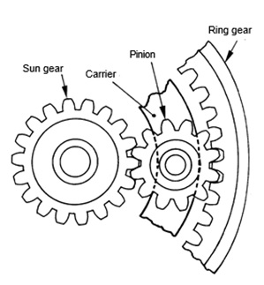
Planetary gears
The planetary gears used have three main parts in the drawing below
1. the ring gear
2. the planet carrier and pinions or planet gears
3. the sun gear

Part of a planetary gear system; the three parts are the ring gear, the planet carrier and the sun gear.
All the gears are in constant mesh and do not slide. The gear ratios are obtained by holding one of the parts stationary with a brake. One of other parts then acts as the driver, and the third part is driven.
Planetary gears get their name from the way in which the pinions rotate and revolve around the sun gear. This is similar to the planets in our solar system, which revolve around the sun
Planetary gear operation
The drawing below shows parts of a planetary gear set. These are a sun gear, a pinion with part of its carrier, and a ring gear. A planetary gear set can operate in either of two ways: non- planetary and planetary. The action will depend on which part is held and which part is the driver.
Part of a planetary gear set; with the sun gear as driver and the ring gear held, the carrier will be driven by planetary action.
Non -Planetary Action
If the carrier is held, the pinion acts as an idler between the sun gear and the ring gear. The pinion revolves on its own shaft and transmits drive between the other two gears. There is no planetary action.
If the sun gear is the driver, the ring gear will be driven at a reduced speed because a small gear is driving a large one. If the ring gear is the driver, the sun gear will be driven at an increased speed because a large gear is driving a small one.
Planetary Action
Planetary action will occur whenever the sun gear or the ring gear are held. In both cases, the pinions will walk around the stationary gear to provide planetary action.
1. If the ring gear is held and the sun gear is the driver, the sun gear will try to rotate the pin- ion.
2. The pinion will try to rotate the ring gear, but it cannot do so because the ring gear is held stationary.
3 However, the pinion must rotate, so it is forced to walk around inside the stationary ring gear, taking the carrier with it
The effect of all this is that the sun gear drives the carrier at a reduced speed.
The gear ratio between the sun gear and the carrier depends on the number of teeth in the sun gear and the 'equivalent' number of teeth in the internal ring gear teeth. The Ring gears has more equivalent teeth than the sun gear, so with the sun gear as driver, there will be a gear reduction between the two parts. (The equivalent number of teeth in the carrier is the number of teeth that it would have if it were an actual toothed gear).
Direction of Rotation of Gears
Gears with external teeth in mesh will rotate in opposite directions. With internal teeth in mesh, the gears will rotate in the same direction. For planetary action, the planet will rotate in the same direction as the gear that is the driver.
Simplified planetary gear operation
The easy way to understand planetary gears is to consider them as a simple train of three spur gears as shown in the drawing below. The spur gears provide similar ratios to a planetary gear set which has a sun gear with 20 teeth and a ring gear with 40 teeth.

Simplified gear trains: (a) train of spur geaars equivalent planetary gear set. Numbers represent the number teeth on each gear.
Because the size of both these gears affects the gear ratio, the carrier can be treated as a gear with 40 + 20 = 60 teeth. (This is the equivalent number of teeth previously mentioned).
In the diagram, if the ring gear is held and the sun gear is the driver, there will be a 20-tooth gear driving 60-tooth (equivalent) gear. This gives a reduction of 3 : 1.
Note that the spur gear train and the planetary gear set will produce different directions of rotation. In the simple gear train, all the gears have external teeth. With the planetary gears there are internal teeth on the ring gear.
Planetary Gear Conditions
The drawing shows the six diffrent conditions that can be produced by a simple planetary gear set. Three of these give a speed reduction, and three give a speed increase. Also with two of these, a reversal of rotation takes place.
Table 1 Planetary gear conditions

DR : driver inc. increase
DN : driven (R) : reverse
Direction of planetary gear rotation
The rotation of the gears in a simple planetary gear set is shown in the three diagrams in the drawing below. As already indicated, the direction of rotation of gears depends on whether external teeth or internal teeth are in mesh. The diagrams should be used to become familiar with what each part does, whether there is an increase or a decrease in speed, and also the direction of rotation.


Simple planetary gears showing rotation; (a) ring gear held, sun gear driven (b) sun gear held, ring gear driven, carrier driven (c) Carrier held, sun gear driver, ring gear driven in reverse direction
Compound planetary gears
A compound planetary gear set is shown in drawing below. This is also referred to as Ravigneaux planetary gearing. It consists of
1. a primary (small) sun gear;
2. a secondary (large) sun gear;
3. a ring or internal gear;
4. a pinion carrier with a set of long (second- ary) pinions and a set of short (primary) pin- ions.
The long pinions connect the secondary sun gear to the ring gear, while the short pinions connect the primary sun gear to the ring gear through the secondary pinions.

Compund planetary gear set used in an automatic transmission.
Table 2 shows the clutches and bands that are applied for the various gear ratios. If the clutches and bands are numbered from 1 to 5 as in the above list, and as they are located in the transmission, then the larger numbers represent the lower gears. See the drawing below.

Arrangement of the torque converter and mechanical components in an automatic transmission for a rear-wheel-drive vehicle.

The torque converter and gear section of an automatic transmission with compund planetary gears; a one-way clutch is used

The front clutch (1) is used with the rear band (4), or with the one-way clutch (5), for first. The front clutch (1) and the front band (3) are used for second, and the front clutch (1) and the rear clutch (2) are used for third. With this transmission, the units are applied progressively from rear to front. The rear clutch and the rear band are applied for reverse.
Power flow in compound planetary gearing
To understand how various gears can be obtained in an automatic transmission, the driver or power flow has to be followed through the various parts of the gearing. This is shown in the illustrations of the compound planetary gear sets in drawing below

Compound planetary gears in low; the carrier is held and drive from the primary sun gear is transfered by both secondary pinions to the ring gear and so to the output shaft.

Note that these are the gear section of drawing, and that the parts of the gearing that are being used are shown darker than the others.
Power transmission control
There are two type of the powershift transmission control are :
1. Automatically and
2. Manually
3. Electronic Control
Powershift Transmission Automatically Control
The hydraulics and controls of an automatic transmission are shown as a simple block diagram indrawing below. The system functions automatically, although the driver has overall control.

Points which relate to the hydraulic section of the diagram are as follows:
1. Fluid the oil pan is delivered by an oil pump to the control valves.
2. Various valves are included in the system.
Some of these regulate the fluid pressure in the system, while others direct fluid to the various parts of the system.
3. Fluid is directed to the torque converter, where it is used for power transmission.
4. Fluid is directed to the friction elements - the clutches and the brakes - where it is used to obtain the gear range selected and for au- tomatic gearshifting.
5. Fluid is circulated through the passages of the lubricating circuit to lubricate bearing surfaces and other parts.
6. Fluid returning through the passages of di- rected through the cooler where it is cooled before being returned to the oil pan. Heat is generated mainly in the torque converter and at the clutches and brakes.
The parts of the system noted above are internal. However, to control the system, there are certain external inputs which can be considered as signals.
Powershift Transmission Manually control
The driver has manual control through the selector lever. A number of selector lever positions are provided.

Selector lever and selector lever positions. The engine will start only in N and P. The lever can be moved freely between the positions shown by the light arrows
Transmissions with electronic controls have sensors which supply information the electronic control unit. The control unit processes the information and sends signals to electrical solenoids in the transmission. The solenoids are used to operate hydraulic valves.
The electronic control system performs functions that would otherwise be done
hydraulically: a road-speed sensor can be used with a governor or instead of a governor, and a throttle-position sensor can be used instead of a throttle valve.
Simple hydraulic system in Powershift Transmission
The essential parts of the hydraulic system in powershift transmission, including a regulator valve and a control valve, are shown in simplified form in drawing below. The fluid is contained within the oil pan and pumped by the oil pump to the regulator valve. The regulator valve regulates the pressure by passing surplus fluid, which it return to the oil pan.
TRANSMISSI
 Reviewed by heri
on
6:28 AM
Rating:
Reviewed by heri
on
6:28 AM
Rating:
Reviewed by heri
on
6:28 AM
Rating:


No comments: