
ENGINE

3524B low altitude engine LH
Shown is the left side of the Low Altitude 797B engine. The Low Altitude engine is used in 797B trucks that operate below 2592 meters (8500 ft.). The engine will derate if operated above this altitude. The Low Altitude engine is equipped with two 3512B dual turbocharged aftercooled engine modules. The Low Altitude engine has four turbochargers; two for the front engine module and two for the rear engine module.797B engine changes include:
* Increased engine gross power from 2535 kW (3400 hp) to 2648 kW (3550 hp).
* Increased flywheel power from 2397 kW (3213 hp) to 2513 kW (3370 hp).
* Changed from a mechanical fuel priming pump to an electrical fuel priming pump.
* Increased maximum fan speed from 500 rpm to 525 rpm.
* The rear engine support castings have changed to allow for the mounting of the new engine package. The front engine supports were lowered in the frame for the same reason. Changes were also made to the ROPS tube mounting plates and the upper radiator mounts.
* Added a pressure sensor to the engine coupling lube system.
* The engine oil renewal system is available as an attachment.

3524B low altitude engine RH.
Shown is the right side of the 797B Low Altitude engine. The fuel priming filters and electrical fuel priming pumps (arrows) are located on this side of the engine.Some of the 797B truck Low Altitude engine information is listed below:
* Serial No. Prefixes:
3524B - 3TN
3512B Front - 1AW
3512B Rear - 2CS
* Performance Specs:
3524B - 0K3587
3512B Front 0K3585
3512B Rear - 0K3586
* Max Altitude - 2591 Meters (8500 ft)
* Gross Power - 2648 kW (3550 hp)
* Net Power - 2513 kW (3370 hp)
* High Idle rpm - 1950
* Full Load rpm - 1750
* Stall Speed rpm - 1744 ± 65 rpm (without torque limiting)
* Torque Limit rpm - 1600 ± 65 rpm
* Boost at Full Load rpm - 193 ± 20 kPa (28 ± 3 psi) (at sea level)
* Boost at Torque Limit rpm - 163 ± 20 kPa (23.7 ± 3 psi) (at sea level)

3524B high altitude engine LH
Shown is the left side of the High Altitude 797B engine. The High Altitude engine is used in 797B trucks that operate between 3050 Meters (10000 ft) to 4575 Meters (15000 ft). The engine will derate if operated below or above these altitudes. The High Altitude engine is equipped with two 3512B quad and series turbocharged aftercooled engine modules. The High Altitude engine has eight turbochargers; four for the front engine module and four for the rear engine module.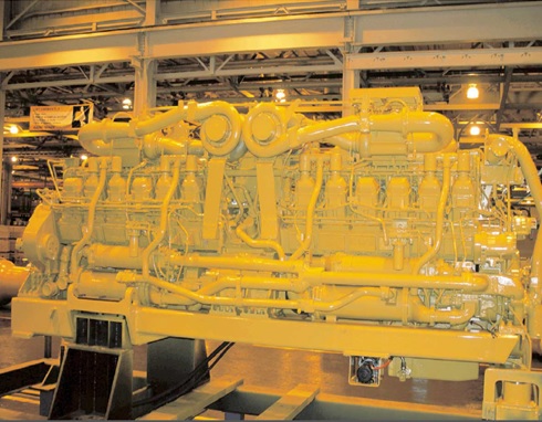
3524B high altitude engine RH.
Shown is the right side of the High Altitude 797B engine.Some of the 797B truck High Altitude engine information is listed below:
* Serial No. Prefixes:
3524B - 3TN
3512B Front - 1AW
3512B Rear - 2CS
* Performance Specs:
3524B - 0K1721
3512B Front - 0K1719
3512B Rear - 0K1720
- Operating Altitude - 3050 Meters (10000 ft) to 4575 Meters (15000 ft)
* Gross Power - 2648 kW (3550 hp)
* Net Power - 2513 kW (3370 hp)
* High Idle rpm - 1950
* Full Load rpm - 1750
* Stall Speed rpm - 1744 ± 65 rpm (without torque limiting)
* Torque Limit rpm - 1600 ± 65 rpm
* Boost at Full Load rpm - 243 kPa (35.2 psi) (at sea level)
* Boost at Torque Limit rpm - ± 20 kPa ( ± 3 psi

Engine Control System
Shown is the electronic control system component diagram for the 3524B engine used in the 797B truck. Fuel injection is controlled by three second generation Advanced Diesel Engine Management (ADEM II) engine Electronic Control Modules (ECMs); one master and two slaves.The Slave ECMs receive most of the input signals from the sensors, switches and senders located on each engine module. The Slave ECMs also receive information from the Master ECM and energize the injector solenoids to control engine timing and speed.
The Slave ECMs send the fuel limit information to the Master ECM and the Master ECM makes sure that both Slave ECMs have the same fuel position (rack). The Master ECM sends governing information to the Slave ECMs through the Controller Area Network (CAN) Data Link which is capable of faster transmission rates than the CAT Data Link.
For example, if the front Slave ECM calculates an air filter restriction in the front engine module, the front Slave ECM will transmit the derate information to the Master ECM and the Master ECM will make sure that both engine modules are derated to the same limits. Therefore, the Master ECM sets the maximum fuel limits.
The Master ECM physically receives the input signals that must be sent to both engine modules. Master ECM inputs are:
* coolant flow
* user defined shutdowns
* throttle back-up
* manual ether injection (auto ether injection is controlled by the Slave ECMs)
* throttle position
* two engine speed timing sensors, one from each engine module
Occasionally Caterpillar will make changes to the internal software (personality module) that controls the performance of the engine. These changes can be performed by using the WinFlash program that is part of the laptop software program, Electronic Technician (ET). ET is used to diagnose and program the electronic controls used in Off-highway Trucks. If using the WinFlash program, a "flash" file must be obtained from Caterpillar and uploaded into the existing ECM personality module.
When installing "flash" files in an Engine Master ECM, ET uses the American Trucking Association (ATA) Data Link. The Slave ECMs are flashed through the CAT Data Link. The ATA and CAT Data Links consist of a pair of twisted wires that connect to the Engine ECMs and the diagnostic connector in the cab. The wires are twisted to reduce electrical interference from unwanted sources such as radio transmissions.
The Master ECM has its own flash file and the Slave ECMs use the same flash file

3524B Engine ECMs
Shown are the three ADEM II Engine ECMs that control the 3524B engine used in the 797B truck.The Master ECM (1) is located above the engine coupling housing between the front and rear 3512B engine modules. The Master ECM is not cooled by fuel because it does not use the injector drivers which create most of the heat in an ECM.
The front Slave ECM (2) is mounted on the front engine module and the rear Slave ECM (3) is mounted on the rear engine module. The Slave ECMs are cooled by fuel because they use the injector drivers to energize the injector solenoids, which create heat.
When reflashing any of the three Engine ECMs, it is not necessary to disconnect the harness from the ECMs. Winflash looks at the ECM serial numbers to tell the ECMs apart. Both of the Slave ECMs should have the same software/personality part number flashed into them. ET, VIMS and the other controls distinguish the ECMs apart on the CAT data link by their MID (Module Identifier)
The Slave ECM software allows the ECM to be programmed to a front or rear engine ECM, thus changing the ECM's MID. This programming is originally done at the Lafayette Engine Plant, and once it is programmed, new software can be flashed WITHOUT reprogramming the control to a front or rear ECM. If a slave ECM is replaced and new software is flashed into it, the control will default to a front engine control. If the slave ECM needs to be changed to a rear slave then the following steps need to take place:
1. Disconnect the front slave ECM.
2. Connect ET to the slave ECM that is to be changed to a rear slave.
3. Go to the configuration screen on ET.
4. Change the Engine Location configuration from a "Front" slave ECM to a "Rear" slave ECM.
Again, once the ECMs are programmed as a front and rear ECM, the software can be reflashed without disconnecting the harness from the ECMs or programming a control as a front or rear ECM

Atmospheric pressure sensors
An atmospheric pressure sensor (1) is located behind both of the Slave ECMs. The Slave ECMs use the atmospheric pressure sensors as a reference for calculating boost and air filter restriction.The sensors are also used for derating the engine at high altitudes. The ECMs will derate the engine at a rate of 1% per kPa to a maximum of 21%. Derating begins at a specific elevation. The elevation specification can be found in the Technical Marketing Information (TMI). If the Engine ECMs detect an atmospheric pressure sensor fault, the ECMs will derate the fuel delivery to 21%. If the Engine ECMs detects an atmospheric and turbocharger inlet pressure sensor fault at the same time, the ECMs will derate the engine to the maximum rate of 34%.
The Engine ECMs also use the atmospheric pressure sensors as a reference when calibrating all the pressure sensors.
The atmospheric pressure sensors are one of the many analog sensors that receive a regulated 5.0 ± .0.5 Volts from the Engine ECMs. The atmospheric pressure sensor output signal is a DC Voltage output signal that varies between 0.2 and 4.8 Volts DC with an operating pressure range between 0 and 111 kPa (0 and 15.7 psi)
To check the output signal of analog sensors, connect a multimeter between the B and C pins of the sensor connector. Set the meter to read DC Volts. The DC Voltage output of the atmospheric pressure sensor should be between 0.2 and 4.8 Volts DC.
"Pull-up voltage" is a voltage supplied from within an ECM through an internal resister which "pulls up" the signal circuit contact on the connector of the control input. Pull-up circuits are used on most sensor and switch inputs of electronic controls. Frequency sensors do not receive a pull-up voltage (except for suspension cylinder pressure sensors). The pull-up voltage is determined by the ECM design and will vary between ECMs. Pull-up voltage sometimes is the same value as the voltage source that powers the sensor, but does not have to be. Remember, pull-up voltage is on the SIGNAL input to the ECM for a given sensor (or switch) and most often HAS NO relationship to the voltage that POWERS the sensor. PWM sensors most often have a pull- up voltage value DIFFERENT than the voltage that powers them. Analog sensors, as used with the engine ECM, most often have a pull-up voltage that is the SAME as the voltage that powers them. The Engine ECM will provide a "pull-up voltage" to the signal circuit of the sensors when the ECM senses an OPEN circuit. The signal circuit is pin C of the 3-pin sensor connectors. The pull-up voltage for the Engine ECM sensors is approximately 6.50 volts.
To test for pull-up voltage, use a digital multimeter set to DC voltage, and use the following procedure (key start switch must be ON):
1. Measure between pins B (analog or digital return) and C (signal) on the ECM side of a sensor connector before it is disconnected. The voltage that is associated with the current temperature or pressure should be shown.
2. Disconnect the sensor connector while still measuring the voltage between pins B and C. If the circuit between the ECM and the sensor connector is good, the multimeter will display the pull-up voltage
The Controller Area Network (CAN) Data Link (2) can be recognized by the shielded cable and the connectors that are also shielded. Inside is a twisted pair of copper wires. The CAN Data Link is used for high speed transmission of data between the Engine ECMs.
To test the CAN Data Link, turn the power to the ECMs OFF and disconnect all of the ECM receptacles. Check the resistance between each ECM receptacle pins. The result should be as follows:
The "A" pin is Negative, the "B" pin is Positive, and the "C" pin is Shield. "A" to "A" = 0 ohms
"B" to "B" = 0 ohms
"A" to "B" = 60 ohms
"A" or "B" to Ground = OPEN

Engine speed/timing sensors.
Two engine speed/timing sensors (1) are positioned near the rear of the left camshaft on both engine modules for a total of four engine speed timing sensors. Two of the sensors, one on each engine module, provide engine speed input to the Master ECM. The Master ECM does not use timing information. The other two sensors, one on each engine module, provide input to the Slave ECMs, which control the engine speed and timing.The engine speed/timing sensor is one of the most important inputs to the engine Slave ECMs. If the engine Slave ECM does not receive an input signal from the engine speed/timing sensors, the engine will not run.
The engine speed/timing sensor receives a regulated 12.5 ± .1.0 Volts from the Engine ECM. To check the output signal of the speed/timing sensor, connect a multimeter between the B and C pins of the speed/timing sensor connector. Set the meter to read frequency. The frequency output of the speed/timing sensor should be approximately:
* Cranking--23 to 40 Hz
* Low Idle--140 Hz
* High Idle--385 Hz
When viewing engine speed in the ET status screen, cranking speed should be between 100 and 250 rpm.
A passive (two wire) engine speed sensor (2) is positioned on top of the rear engine module flywheel housing. The passive speed sensor uses the passing teeth of the flywheel to provide a frequency output. The passive speed sensor sends the engine speed signal to the Transmission and Brake/Cooling ECMs.
The signal from the passive speed sensor is used for several purposes. They are:
* Torque converter lockup clutch slippage monitoring
* Shift time calculations
* Transmission Output Speed (TOS) ratification
* Transmission clutch slippage monitoring
* Automatic Retarder Control (ARC) engine control speed
* Engine running signal for Hoist operation
The output signal of the passive speed sensor can also be checked by connecting a multimeter between the two pins of the speed sensor connector and setting the meter to read frequency.
NOTE: Turn ON the engine shutdown switch (see Visual No. 41) during the cranking test to prevent the engine from starting. The cranking speed and frequency output will vary depending on weather and machine conditions. When viewing engine speed in the ET status screen, cranking speed should be between 100 and 250 rpm.
The hoist system will not function without a valid engine speed signal.

Timing calibration connector (arrow)
A timing calibration connector (arrow) is located on the right front corner of each engine module. The timing of both engine modules must be performed separately. If the engine requires timing calibration, a timing calibration sensor (magnetic pickup) is installed in the flywheel housing and connected to the timing calibration connector.Using the Caterpillar ET service tool, timing calibration is performed automatically for the speed/timing sensors. The desired engine speed is set to 800 rpm. This step is performed to avoid instability and ensures that no backlash is present in the timing gears during the calibration.
Timing calibration improves fuel injection accuracy by correcting for any slight tolerances between the crankshaft, timing gears, and timing wheel.
Timing calibration is normally performed after the following procedures:
1. ECM replacement
2. Speed/timing sensor replacement
3. Timing wheel replacement
NOTE: The engine flywheels have two threaded timing holes located at different distances from the flywheel center. The two timing holes allow the engines to be pin timed and dynamically timed from either side of the flywheel housing.

Throttle position sensor (arrow)
The throttle position sensor (arrow) provides the desired throttle position to the Master ECM. If the Master ECM detects a fault in the throttle position sensor, the throttle back-up switch (see Visual No. 61) can be used to increase the engine speed to 1300 rpm.The throttle position sensor receives a regulated 8.0 ± 0.5 Volts from the Master ECM. The throttle position sensor output signal is a Pulse Width Modulated (PWM) signal that varies with throttle position and is expressed as a percentage between 0 and 100%.
To check the output signal of the throttle position sensor, connect a multimeter between the B and C pins of the throttle position sensor connector. Set the meter to read duty cycle. The duty cycle output of the throttle position sensor should be:
* Low Idle--16 ± 6%
* High Idle--85 ± 4%

Crankcase pressure sensor (arrow)
A crankcase pressure sensor (arrow) is located on the left side of both engine modules. The crankcase pressure sensors provide input signals to the Slave ECMs. The Slave ECMs provides the signal to the VIMS, which informs the operator of the crankcase pressure.High crankcase pressure may be caused by worn piston rings or cylinder liners.
If crankcase pressure exceeds 3.6 kPa (.5 psi) or 14.4 inches of water, a high crankcase pressure event will be logged. No factory password is required to clear this event.

EUI fuel injector solenoid
Shown is the top of a cylinder head with the valve cover removed. The most important output from the Engine ECM is the Electronic Unit Injection (EUI) injector solenoid (1). One injector is located in each cylinder head. The Slave ECMs analyze all of the inputs and send signals to the injector solenoids to control engine timing and speed.Engine timing is determined by controlling the start and end time that the injector solenoid is energized. Engine speed is determined by controlling the duration that the injector solenoid is energized.
When 3500B injectors are manufactured, they are calibrated for precise injection timing and fuel discharge. After the calibration, a four digit
trim code number (2) is etched on the injector tappet surface. The E-trim code identifies the injector's performance range. If no code is available, "1100" is the default number to enter.
When the injectors are installed into an engine, the trim code number of each injector is entered into the personality module (software) of the Engine ECM using the ET service tool. The software uses the trim code to compensate for the manufacturing variations in the injectors and allows each injector to perform as a nominal injector. When an injector is serviced, the new injector's trim code should be programmed into the Engine ECM. If the new trim code is not entered, the previous injector's characteristics are used. The engine will not be harmed if the new code is not entered, but the engine will not provide peak performance.

Events logged by Engine ECMs
The 3524B Engine ECMs log several data events that could cause damage to the engine. Some of the events require factory passwords to clear from the ECM memory. The events logged by the Engine ECMs, their maximum derate, and their trip points are listed below:Air filter restriction: Greater than 6.25 kPa (25 in. of water). Maximum derate of 21%. Factory password required.
If the atmospheric and turbo inlet pressure sensors both fail at the same time, a derate of 34% will occur.
Low oil pressure: From less than 44 kPa (6.4 psi) at LOW IDLE to less than 250 kPa (36 psi) at HIGH IDLE. Factory password required.
High coolant temperature: Greater than 107°C (226°F). Factory password required.
Engine overspeed: Greater than 2200 rpm. Factory password required.
Oil filter restriction: Greater than 70 kPa (10 psi). No factory password required. Greater than 200 kPa (29 psi). Factory password required.
Coolant flow low: Factory password required.
Fuel filter restriction: Greater than 138 kPa (20 psi). No factory password required.
User defined shutdown: The customer has the option of installing systems that will shut down the engine if desired. If the installed system sends a ground signal to the Master ECM at connector J1 pin 19, a user defined shutdown will occur. Factory password required.
The VIMS will shutdown the engine for any of the following conditions:
* Engine oil level low
* Engine oil pressure low
* Engine coolant temperature high
* Engine coolant level low
* Aftercooler coolant level low
The engine will only shutdown when ground speed is 0 and the parking brake is ENGAGED. The Engine ECM does not log events for VIMS initiated engine shutdowns.
Exhaust temperature high: Greater than 750°C (1382°F). Maximum derate of 20%. Factory password required.
Engine oil level low: No factory password required.
Aftercooler coolant temperature high: Greater than 107°C (226°F). Factory password required.
Prelube override: Override the engine oil prelube system with the key start switch. Factory password required (see Visual No. 100).
Crankcase pressure high: Greater than 3.6 kPa (.5 psi) or 14.4 inches of water. No factory password required.

Engine ECMs control other systems
The Engine ECMs regulate other systems by energizing solenoids or relays. Mostly, the Slave ECMs energize the relays or solenoids, but the Master ECM has the overall control so that the two engine modules stay in sync. Some of the systems controlled by the Engine ECMs are:Ether Injection: The Engine ECMs will automatically inject ether from the ether cylinders during cranking. The duration of automatic ether injection is dependent on jacket water coolant temperature. The duration will vary from 10 to 130 seconds.
The operator can also inject ether manually with the ether switch in the cab on the center console (see Visual No. 61). The manual ether injection duration is 5 seconds. Ether will be injected only if the engine coolant temperature is below 10°C (50°F) and engine speed is below 1900 rpm
Cool Engine Elevated Idle: The Engine ECMs provides an elevated engine idle speed of 1300 rpm when the engine coolant temperature is below 60°C (140°F). The rpm is gradually reduced to 1000 rpm between 60°C (140°F) and 71°C (160°F). When the temperature is greater than 71°C (160°F), the engine will idle at Low Idle (700 rpm).
Increasing the low Idle speed helps prevent incomplete combustion and overcooling. To temporarily reduce the elevated idle speed, the operator can release the parking brake or depress the throttle momentarily, and the idle speed will decrease to LOW IDLE for 10 minutes.
Cold Cylinder Cut-out: The cold cylinder cut-out strategy provides:
Reduced white exhaust smoke (unburned fuel) after start-up and during extended idling in cold weather
Minimizes the time in Cold Mode
Reduces the use of ether injection.
After the engine is started and the automatic ether injection system has stopped injecting ether, the Engine ECMs will cut out one cylinder at a time to determine which cylinders are firing. The Engine ECMs will disable some of the cylinders that are not firing. The ECMs can identify a cylinder which is not firing by monitoring the fuel rate and engine speed during a cylinder cutout. The ECMs average the fuel delivery and analyzes the fuel rate change during a cylinder cutout to determine if the cylinder is firing. Disabling some of the cylinders during Cold Mode operation will cause the engine to run rough until the coolant temperature increases above the Cold Mode temperature. This condition is normal, but the operator should be aware it exists to prevent unnecessary complaints.
Engine Start Function: The Engine Start function is controlled by the Engine ECMs and the Chassis ECM. The Engine ECMs provide signals to the Chassis ECM regarding the engine speed and the condition of the engine prelubrication system. The Chassis ECM will energize the starter relay only when:
The shift lever is in NEUTRAL.
The parking brake is ENGAGED.
The engine speed is 0 rpm.
The engine prelubrication cycle is complete or turned OFF.
NOTE: To protect the starter, the starter is disengaged by the Chassis ECM when the engine rpm is above 300 rpm.

Engine oil prelubrication.
Engine Oil Prelubrication: Engine oil prelubrication is controlled by the Engine ECMs and the Chassis ECM. The Chassis ECM signals the Engine ECMs when to energize the prelubrication pump relay (not shown). The Engine ECMs signal the Chassis ECM to crank the engine when:* Engine oil pressure is 3 kPa (.4 psi) or higher.
* The prelubrication pump (arrow) has run for 17 seconds. (If the system times out after 17 seconds, a prelubrication time out fault is logged in the Engine ECM.)
* The engine has been running in the last 2 minutes.
* Coolant temperature is above 50°C (122°F).
The engine oil prelubrication system can be bypassed to allow for quick starts. To override the prelubrication system, turn the key start switch to the CRANK position for a minimum of two seconds. The Chassis ECM will begin the pre-lube cycle. While the pre-lube cycle is active, turn the key start switch to the OFF position. Within 10 seconds, turn the key start switch back to the CRANK position. The Chassis ECM will engage the starter relay.
If the engine oil prelubrication system is bypassed using the above procedure, the Engine ECM will log a pre-lube override event that requires a factory password to clear.
NOTE: The ET service tool can enable or disable the prelubrication feature in the Engine ECMs.

Engine oil renewal system components.
Engine Oil Renewal System (attachment): Located on the left side of the engine are the components of the engine oil renewal systems. There is a separate oil renewal system on the front and the rear engine modules. Shown is the front engine module. On each engine module, engine oil flows from the engine block through an oil filter (1) to the engine oil renewal solenoid valve (2). When the solenoid is energized and de- energized, a small amount of oil flows from the engine oil renewal solenoid valve into the fuel line that returns to the fuel tank. The engine oil returns to the fuel tank with the return fuel. The engine oil mixes with the fuel in the tank and flows with the fuel to the EUI injectors to be burned.If the machine is equipped with the engine oil renewal system, the engine oil filters, the engine oil renewal system filter, the primary fuel screen, and the secondary fuel filters must all be changed at 500 hour intervals. The engine oil should be changed at least once per year or 4000 service meter hours.
Engine oil samples must be taken regularly to ensure that the soot level of the engine oil is in a safe operating range.
The Slave ECMs regulate the amount of oil that is injected by the engine oil renewal solenoid. Several parameters must be met before the ECM will allow the injection of oil through the engine oil renewal system. The parameters that must be met are:
* Fuel position is greater than 10.
* Engine rpm is between 1100 and 1850 rpm.
* Jacket water temperature is between 63°C (145°F) and 107°C (225°F).
* Oil filter differential pressure at high idle with warm oil is less than 70 kPa (10 psi).
* Fuel filter differential pressure is less than 140 kPa (20 psi).
* Fuel level is greater than 10%.
* Engine oil level switches are sending a valid signal to the Engine ECM.
* Engine has been running more than five minutes.
The engine oil renewal system can be turned ON or OFF with the ET service tool. The amount of oil injected can also be adjusted by programming the Slave ECMs with the ET service tool. The factory setting shown in the service tool is "0" and is equivalent to a 0.5% oil to fuel ratio. The ratio can be changed with the service tool from minus 50 (-50) to plus 50 (+50), which is equivalent to 0.25% to 0.75% oil to fuel ratios.

Oil renewal solenoid valve.
Shown is a sectional view of the engine oil renewal solenoid valve. When the Engine Slave ECM determines that oil can be injected into the fuel return line, a Pulse Width Modulated (PWM) duty cycle signal is sent to the oil renewal solenoid. The solenoid is turned ON for 1.25 seconds and turned OFF for 1.25 seconds for a total cycle time of 2.5 seconds. How many times the solenoid is turned ON and OFF will determine the volume of oil that is injected. Oil is injected when the solenoid is turned ON and oil is also injected when the solenoid is turned OFF. When the solenoid is turned ON, engine oil flows to the left side of the piston and pushes the piston to the right.The volume of oil that is trapped between the right side of the piston and the check ball compresses the spring and opens the passage to the fuel return line. When the solenoid is turned OFF, engine oil flows to the right side of the piston and pushes the piston to the left. The volume of oil that is trapped between the left side of the piston and the check ball compresses the spring and opens the passage to the fuel return line. The volume of delivery is equal to 3.04 ml/cycle
(0.1 oz/cycle)

Cooling Systems
Shown is the cooling system shunt tank located above the radiator. The shunt tank provides a positive pressure at the coolant pump inlets to prevent cavitation during high flow conditions.The cooling system is divided into two systems. The two systems are the jacket water cooling system and the aftercooler cooling system. The jacket water cooling system uses the cores on the right side of the radiator (approximately 54% of the total capacity). The jacket water cooling system temperature is controlled by temperature regulators (thermostats).
The aftercooler cooling system uses the cores on the left side of the radiator (approximately 46% of the total capacity). The aftercooler cooling system does not have thermostats in the circuit. The coolant flows through the radiator at all times to keep the turbocharged inlet air cool for increased horsepower.
The only connection between these two systems is a small hole in the separator plate in the shunt tank. The small hole in the shunt tank prevents a reduction of coolant from either of the two systems if leakage occurs in one of the separator plates in the radiator top or bottom tank. When servicing the cooling systems, be sure to drain and fill both systems separately.
The coolant levels are checked at the shunt tank. Use the gauges (1) on top of the shunt tank to check the coolant levels.
A coolant level switch (2) is located on each side of the shunt tank to monitor the coolant level of both cooling systems (guard removed for viewing switch). The coolant level switches provide input signals to the VIMS, which informs the operator of the engine coolant levels.
Pressure relief valves (3) prevent the cooling systems from becoming over pressurized. If a cooling system overheats or if coolant is leaking from a relief valve, clean or replace the relief valve.

Jacket Water Cooling System
Shown is the jacket water cooling system circuit. Coolant flows from the jacket water pump through the coolers to the engine blocks. Coolant flows through the engine blocks and the cylinder heads.From the cylinder heads, the coolant flows to the temperature regulators (thermostats) and either goes directly to the water pump through the bypass tube or to the radiator (depending on coolant temperature).
The shunt tank increases the cooling capacity and provides a positive pressure at the coolant pump inlet to prevent cavitation during high flow conditions

Jacket water pump
The jacket water pump (1) is located on the right side of the front engine module. The pump draws coolant from the engine through bypasstube (2) until the temperature regulators (thermostats) open. The thermostats are located in the housing at the top of the bypass tube. When the thermostats are open, coolant flows through the radiator to the water pump inlet.

Jacket water coolant temperature sensor (arrow)
The front engine module jacket water coolant temperature sensor (arrow) is located in the jacket water thermostat housing. Another coolant temperature sensor is located in the rear engine module (see VisualNo. 114). The Engine ECMs use the coolant temperature sensor information for cold mode functions such as timing changes, elevated idle, cold cylinder cut-out, ether injection, and others.
The coolant temperature sensor is also the main parameter used to control the engine fan speed.
If the jacket water cooling system temperature increases above 107°C (226°F), the Engine ECM will log an event that requires a factory password to clear.

Coolant flow warning switch (arrow)
Coolant flows from the jacket water pump, past the coolant flow warning switch (arrow), and through the various system oil coolers (engine, power train, front brake, and steering/fan drive).The coolant flow switch sends an input signal to the master Engine ECM. The Master ECM provides the input signal to the VIMS, which informs the operator of the coolant flow status.
If the Master ECM detects a low coolant flow condition, a low coolant flow event will be logged. A factory password is required to clear this event.

Engine oil cooler and Power train oil coolers.
Shown is the right side of the engine. The engine oil coolers (1) and the power train oil coolers (2) are visible in this view.Jacket water coolant flows through the engine oil cooler and the power train oil cooler on the front engine module and enters the front engine module block at the right rear.
Jacket water coolant also flows through the engine oil cooler and the power train oil cooler on the rear engine module. Coolant flows through these coolers to the front brake oil coolers and the steering/fan drive oil cooler located on the right frame (see next visual). Jacket water coolant flows through the front brake oil coolers and the steering/fan drive oil cooler and enters the rear engine module block at the right rear.
Coolant flows through the engine blocks and the cylinder heads. From the cylinder heads, the coolant flows to the temperature regulators and either goes directly to the water pump through the bypass tube or to the radiator (depending on the temperature of the coolant.

Front brake oil coolers and Steering/fan drive oil cooler.
Jacket water coolant flows from the engine and power train oil coolers on the rear engine module through the two front brake oil coolers (1) and the steering/fan drive oil cooler (2). Oil flows from these coolers back to the rear engine module block.An S•O•S coolant analysis tap (3) for the jacket water cooling system is located in the oil cooler bottom tank.

Aftercooler Cooling System
Shown is the aftercooler cooling system circuit. Aftercooler coolant flows from the radiator and the shunt tank to the aftercooler water pump. Coolant flows from the aftercooler pump through the front and rear engine module aftercoolers and the spring coupling oil cooler to the rear brake oil coolers. Coolant flows through the rear brake oil coolers and returns to the radiator top tank. There are no temperature regulators (thermostats) in the aftercooler cooling system circuit.The shunt tank increases the cooling capacity and provides a positive pressure at the pump inlet to prevent cavitation during high flow conditions.
The air compressor is also cooled by the aftercooler cooling system circuit.

Aftercooler water pump
The auxiliary (aftercooler) water pump (1) for the aftercooler cooling system is located on the left side of the front engine module. Coolant enters the aftercooler water pump from the radiator or the shunt tank supply tube (2). Coolant flows from the pump to the aftercooler cores through the large tube (3).
Front engine module aftercooler
Shown is the aftercooler (1) on the front engine module. Aftercooler coolant flows from the pump through the front engine module aftercooler and through the tube (2) to the rear engine module. Coolant flows from the front of the aftercooler and exits out the rear of the aftercooler.Also shown is the front engine module aftercooler coolant temperature sensor (3). The sensor is located in a tube at the rear of the aftercooler. Coolant flows past the sensor after it exits the front aftercooler. There is another aftercooler coolant temperature sensor at the rear of the rear engine module.
If the aftercooler cooling system temperature increases above 107°C (226°F), the Engine ECM will log an event that requires a factory password to clear.

Engine coupling oil cooler (arrow)
Shown is the engine coupling oil cooler (arrow). Aftercooler coolant is used to cool the oil that flows to the engine coupling.A separate oil system is used to cool the engine coupling. Oil flows from the engine coupling oil pump through the oil cooler and enters the engine coupling housing through a supply tube. Oil is sprayed on the spring coupling and falls to the bottom of the coupling housing to be scavenged.

Rear engine module aftercooler
Shown is the aftercooler (1) on the rear engine module. Aftercooler coolant flows from the aftercooler pump through the rear engine module aftercooler and through the tube (2) to the rear brake oil coolers. Coolant flows from the front of the aftercooler and exits out the rear of the aftercooler.Shown is the rear engine module aftercooler coolant temperature sensor (3). The sensor is located in a tube at the rear of the aftercooler.
Coolant flows past the sensor after it exits the rear aftercooler and before it enters the rear brake oil coolers. There is another aftercooler coolant temperature sensor at the rear of the front engine module.
Also shown is the rear engine module jacket water coolant temperature sensor (4). The sensor is located in a manifold at the right rear corner of the engine. Typically, the right rear corner of an engine runs the hottest because it is at the end of the oil and coolant flow path.
If the aftercooler or jacket water cooling system temperature increases above 107°C (226°F), the Engine ECM will log an event that requires a factory password to clear.

Rear brake oil coolers
Aftercooler coolant flows from the rear engine module through the rear brake oil coolers (1). Coolant flows from the top of the coolers and exits out the bottom. Aftercooler coolant then flows through the tube (2) and returns to the radiator top tank.An S•O•S coolant analysis tap (3) for the aftercooler cooling system is located in the oil cooler bottom tank.

Lubrication System
The engine oil pump draws oil from the oil pan through a screen. The engine also has a scavenge pump to transfer oil from the shallow end of the oil pan to the main sump. Oil flows from the pump through an engine oil cooler to the oil filters. The oil flows through the filters and enters the engine cylinder block to clean, cool and lubricate the internal components and the turbochargers.Some trucks are equipped with the attachment engine oil renewal system. Engine oil flows from the engine block through an oil filter to the engine oil renewal solenoid valve. When the solenoid is energized and de- energized, a small amount of oil flows from the engine oil renewal solenoid valve into the fuel line that returns to the fuel tank. The engine oil returns to the fuel tank with the return fuel. The engine oil mixes with the fuel in the tank and flows with the fuel to the EUI injectors to be burned.

Engine oil lubrication systems
Shown is the 3524B front engine module oil pump. Both engine modules have their own oil lubrication system. The engine oil pumps are located on the right front side of the engine modules. The pumps draw oil from the oil pans through a screen. The relief valves (1) for the lubrication systems are located on the pumps.The engine modules also have a scavenge pump to transfer oil from the shallow end of the oil pan to the main sump.
Oil flows from the pump through an engine oil cooler (2) to the engine oil filters located on the left side of the engine.

Engine oil filters
Oil flows from the engine oil coolers to the three oil filters located on the left side of both engine modules. The oil flows through the filters and enters the engine cylinder block to clean, cool, and lubricate the internal components and the turbochargers. Engine oil should be added at the fill tube (1) and checked with the dipstick (2).The engine lubrication system is equipped with two oil pressure sensors (3). A sensor is located on each end of the oil filter base. One sensor measures engine oil pressure before the filters. The other sensor
measures oil pressure after the filters. The sensors provide input signals to the engine Slave ECMs. The engine Slave ECMs provide the input signals to the VIMS, which informs the operator of the engine oil pressure. Together, these sensors inform the operator if the engine oil filters are restricted.
If the engine oil pressure is less than 44 kPa (6.4 psi) at low idle to less than 250 kPa (36 psi) at high idle, the Engine ECM will log an event that requires a factory password to clear.
If the oil filter restriction exceeds 70 kPa (10 psi), a low oil filter restriction event will be logged. No factory password is required to clear this event. If the oil filter restriction exceeds 200 kPa (29 psi), a high oil filter restriction event will be logged. A factory password is required to clear this event.
An engine oil level switch (4) provides input signals to the engine Slave ECMs. The engine Slave ECMs provide the signal to the VIMS, which informs the operator of the engine oil level.
The oil level switch tells the operator when the engine oil level is low and it is unsafe to operate the truck without causing damage to the engine. The ENG OIL LEVEL LOW message is a Category 2 or 3 Warning.
On both engine modules, the fitting (5) can be used to drain the engine oil that is trapped above the filters. Do not add oil through the fitting because unfiltered oil will enter the engine. Any contamination could cause damage to the engine
NOTICE
When changing the engine oil filters, drain the engine oil that is trapped above the oil filters through the fitting (5) to prevent spilling the oil. Oil added to the engine through the fitting will go directly to the main oil galleries without going through the engine oil filters. Adding oil to the engine through the fitting may introduce contaminants into the system and cause damage to the engine.

Fuel System
Fuel is pulled from the tank through the primary fuel screen by the fuel transfer pumps on the front and the rear engine modules.On the rear engine module, fuel flows from the transfer pump through the rear Slave ECM to the secondary fuel filters.
On the front engine module, fuel flows from the transfer pump through the secondary fuel filters to the front Slave ECM.
Fuel then flows through the fuel injectors in the cylinder heads. Return fuel from the injectors flows through the bottom of the fuel pressure regulators and returns to the fuel tank through the top of the pressure regulators. The fuel pressure regulators maintain 372 to 737 kPa (54 to 107 psi) in the fuel lines at Full Load rpm
If equipped with the attachment engine oil renewal system, engine oil
flows from the engine block through an oil filter to the engine oil renewal solenoid valve. When the solenoid is energized and de-energized, a small amount of oil flows from the engine oil renewal solenoid valve into the fuel line that returns to the fuel tank. The engine oil returns to the fuel tank with the return fuel. The engine oil mixes with the fuel in the tank and flows with the fuel to the EUI injectors to be burned.lectric
Two secondary fuel filters are located above the engine oil filters on the left side of the front and the rear engine modules. Located above the fuel filters is a switch that controls the electrical fuel priming pump. A 10 amp circuit breaker protects the fuel priming pump electrical circuit. During operation of the electrical fuel priming system, fuel flows from the fuel transfer pump through the fuel priming filter and the check valve to the secondary fuel filters and the rest of the fuel system. The check valve prevents fuel from flowing backwards through the fuel priming system during normal operation. The main function of the fuel priming system is to fill the secondary fuel filters after a fuel filter change..

Primary fuel screen
The fuel tank is located on the left side of the truck. Fuel is pulled from the tank through the primary fuel screen (1) by the fuel transfer pumps located on the right side of both engine modules behind the engine oil pumps. The fuel shutoff valve (2) is shown to the left of the primary fuel screen. The valve is shown in the ON position. Open the drain valve (3) to remove condensation from the fuel tank.A fuel level sensor (4) is also located on the fuel tank. The fuel level sensor emits an ultrasonic signal that bounces off a metal disk on the bottom of a float. The time it takes for the ultrasonic signal to return is converted to a Pulse Width Modulated (PWM) signal. The PWM signal changes as the fuel level changes.
The fuel level sensor receives 24 Volts from the VIMS Main Module. To check the supply voltage of the sensor, connect a multimeter between Pins 1 and 2 of the sensor connector. Set the meter to read "DC Volts."
The fuel level sensor output signal is a Pulse Width Modulated (PWM) signal that varies with the fuel level. To check the output signal of the fuel level sensor, connect a multimeter between Pins 2 and 4 of the fuel level sensor connector. Set the meter to read "Duty Cycle." The duty cycle output of the fuel level sensor should be approximately 6% at 0 mm (0 in.) of fuel depth and 84% at 2000 mm (78.8 in.) of fuel depth.

Fuel transfer pump
There are two fuel transfer pumps, one on each engine module. The fuel transfer pumps (1) are located behind the engine oil pumps. The fuel transfer pumps contain a bypass valve (2) to protect the fuel system components from excessive pressure. The bypass valve setting is 860 kPa (125 psi), which is higher than the setting of the fuel pressure regulator (see Visual No. 123). Fuel flows from the transfer pumps through the engine Slave ECMs and the secondary fuel filters located on the left side of the engine.Also shown is the fuel priming filter (3) and the electrical fuel priming pump (4). During operation of the electrical fuel priming system, fuel flows from the fuel transfer pump through the hose (5), the fuel priming filter, the check valve (6), and the hose (7) to the secondary fuel filters and the rest of the fuel system. The check valve prevents fuel from flowing backwards through the fuel priming system during normal operation.
The main function of the fuel priming system is to fill the secondary fuel filters after a fuel filter change. The fuel priming system can also be used to fill the fuel system with fuel if the engine has run out of fuel. If the engine has run out of fuel, the fuel return line must be blocked during priming in order to force fuel into the injectors
Fuel only flows through the fuel priming filters when the electrical fuel priming pump is running. Generally, the fuel priming filters do not need to be changed through the life of the engine. Service these filters only as needed.
NOTE: If the engine has run out of fuel and the fuel system requires priming, it may be necessary to block the fuel return line during priming to force the fuel into the injectors.

Secondary fuel filters
Two secondary fuel filters are located above the engine oil filters on the left side of the front and the rear engine modules. Located above the fuel filters is the switch (1) that controls the electrical fuel priming pump. A 10 amp circuit breaker (2) protects the fuel priming pump electrical circuit.Fuel filter restriction is monitored with a fuel filter bypass switch (3) located on the fuel filter base. The fuel filter bypass switches provide input signals to the engine Slave ECMs. The Slave ECMs provide signals to the VIMS, which informs the operator if the secondary fuel filters are restricted.
If fuel filter restriction exceeds 138 kPa (20 psi), a fuel filter restriction event is logged. No factory password is required to clear this event.
Fuel flows from the fuel filter base through the Electronic Unit Injection (EUI) fuel injectors and the fuel pressure regulator and then returns to the fuel tank. The injectors receive 4 1/2 times the amount of fuel needed for injection. The extra fuel is used for cooling.

Fuel pressure tubes to injectors
Fuel flows from the fuel filter base through the steel tubes (1) to the EUI fuel injectors. Return fuel from the injectors flows through the fuel pressure regulator (2) before returning to the fuel tank. Fuel pressure is controlled by the fuel pressure regulator.Fuel pressure should be 372 to 737 kPa (54 to 107 psi) at Full Load rpm

Air Induction and Exhaust System
The Low Altitude engine is equipped with two 3512B dual turbocharged aftercooled engine modules. The Low Altitude engine has four turbochargers; two for the front engine module and two for the rear engine module. This schematic shows the air flow through the air induction and exhaust system of one of the Low Altitude 3512B engine modules used in the 797B truck.The clean air from the filters enters the compressor side of the turbochargers. The compressed air from the turbochargers flows to the aftercooler. After the air is cooled by the aftercooler, the air flows to the cylinders and combines with the fuel for combustion.
The two turbochargers are driven by the exhaust gasses from the cylinders which enters the turbine side of the turbochargers. The exhaust gasses flow through the turbochargers, the exhaust piping, and the mufflers

Air induction and exhaust system
The High Altitude engine is equipped with two 3512B quad and series turbocharged aftercooled engine modules. The High Altitude engine has eight turbochargers; four for the front engine module and four for the rear engine module. This schematic shows the air flow through the air induction and exhaust system of one of the High Altitude 3512B engine modules used in the 797B truck.The clean air from the filters enters the larger low pressure turbochargers. The compressed air from the low pressure turbochargers flows to the inlet of the smaller high pressure turbochargers. After additional compression by the high pressure turbochargers, the air flows to the aftercooler. After the air is cooled by the aftercooler, the air flows to the cylinders and combines with the fuel for combustion.
The turbochargers are driven by the exhaust gasses from the cylinders. The exhaust gasses first enter the smaller high pressure turbochargers. The exhaust from the high pressure turbochargers flows to the larger low pressure turbochargers. The exhaust gasses then flow through the low pressure turbochargers, the exhaust piping, and the mufflers

Large primary element
Two filter elements are installed in the filter housings. The large element is the primary element and the small element is the secondary element.Air intake system tips:
* The primary element can be cleaned a maximum of six times.
* Never clean the secondary element for reuse. Always replace the secondary element.
* Air filter restriction causes black exhaust smoke and low power.
* A .6°C (1°F) increase in intake temperature increases exhaust temperature 1.8°C (3°F).
* For every 250 mm (10 in.) of water restriction above 500 mm (20 in.) of water in an air filter, the inlet temperature increases 60°C (100°F).
* Exhaust temperature should not exceed 750°C (1382°F).
Located below the air filter housings are the air filter dust valves (arrow). Check the dust valves for plugging. If necessary, disconnect the clamp and open the cover for further cleaning.
The dust valve is OPEN when the engine is OFF and closes when the engine is running. The dust valve must be flexible and close when the engine is running or the precleaner will not function properly and the air filters will have a shortened life. Replace the rubber dust valve if it becomes hard and not flexible.

Turbocharger inlet pressure sensor (arrow)
The turbocharger inlet pressure sensor (arrow) for the rear engine module is located in a tube between the air filters and the turbochargers. The engine Slave ECMs use the turbocharger inlet pressure sensor in combination with the atmospheric pressure sensor to determine air filter restriction. The Slave ECMs provide the input signals to the VIMS, which informs the operator of the air filter restriction.If air filter restriction exceeds 6.25 kPa (25 in. of water), an air filter restriction event will be logged, and the ECMs will derate the fuel delivery (maximum derating of 21%) to prevent excessive exhaust temperatures. A factory password is required to clear this event. If the Engine ECMs detect a turbocharger inlet pressure sensor fault, the ECMs will derate the engine to the maximum rate of 21%. If the Engine ECMs detect a turbocharger inlet and atmospheric pressure sensor fault at the same time, the ECMs will derate the engine to the maximum rate of 34%.

3512B low altitude engine modules have two turbochargers
Shown is the rear 3512B Low Altitude engine module used in the 797B truck. Both engine modules are equipped with two turbochargers.The turbochargers are driven by the exhaust gasses from the cylinders which enters the turbine side (1) of the turbochargers. The exhaust gasses flow through the turbochargers, the exhaust piping, and the mufflers.
The clean air from the filters enters the compressor side of the turbochargers. The compressed air from the turbochargers flows to the aftercoolers (2). After the air is cooled by the aftercoolers, the air flows to the cylinders and combines with the fuel for combustion.

3512B high altitude engine modules have four turbochargers
Shown are the four turbochargers on the rear engine module of a High Altitude engine.The clean air from the filters enters the larger low pressure turbochargers (1). The compressed air from the low pressure turbochargers flows to the inlet of the smaller high pressure turbochargers (2). After additional compression by the high pressure turbochargers, the air flows to the aftercooler (3). After the air is cooled by the aftercooler, the air flows to the cylinders and combines with the fuel for combustion.
The turbochargers are driven by the exhaust gasses from the cylinders. The exhaust gasses first enter the smaller high pressure turbochargers. The exhaust from the high pressure turbochargers flows to the larger low pressure turbochargers. The exhaust gasses then flow through the low pressure turbochargers, the exhaust piping, and the mufflers

Exhaust temperature sensor (arrow)
An exhaust temperature sensor (arrow) is located in each exhaust manifold before the turbochargers. The four exhaust temperature sensors provide input signals to the engine Slave ECMs. The Slave ECMs provide the input signals to the VIMS, which informs the operator of the exhaust temperature.Some causes of high exhaust temperature may be faulty injectors, plugged air filters, or a restriction in the turbochargers or the muffler.
If the exhaust temperature is above 750°C (1382°F), the Engine ECMs will derate the fuel delivery to prevent excessive exhaust temperatures. The ECM will derate the engine by 2% for each 30 second interval that the exhaust temperature is above 750°C (1382°F) (maximum derate of 20%). The ECM will also log an event that requires a factory password to clear.

Turbo outlet pressure sensor (arrow)
Shown is the turbocharger outlet pressure sensor (arrow) for the front engine module. The turbocharger outlet pressure sensors send input signals to the Slave ECMs. The Slave ECMs compare the value of the turbo outlet pressure sensors with the value of the atmospheric pressure sensors and calculate boost pressures.The best way to check for a power problem is to compare the truck performance with the rimpull charts in the performance handbook (SEBD0343). The truck should be able to climb a grade in the same gear as specified in this publication.
If an engine power problem is suspected, check the boost pressure, and the fuel rack position at full load rpm. If the boost pressure and the fuel rack position is within spec at full load rpm, the engine is not the problem and other systems such as the torque converter should be checked
To check the boost pressure and the fuel rack position at full load rpm, the truck must be operated in FIRST GEAR with the throttle at MAXIMUM and the retarder gradually engaged. Traveling up a grade is best as long as the engine rpm does not fall below the full load rpm specification during the test. Gradually engage the retarder until the full load rpm is displayed. When the full load rpm is displayed, record the boost pressure and the fuel rack position. If the measurements are within the specifications at full load rpm, the engine is operating correctly.

NOTE: The boost specs are at sea level and assume no altitude derate. For example, on a low altitude engine, during torque stall, at 1600 rpm and rack position below 182, the boost pressure at sea level will be 23.7 ± 12%. At an atmospheric pressure of 73 kPa (11 psi), the boost pressure will be 19.7 ± 12%. Boost pressure will vary with atmospheric temperature and pressure
Generally, torque converter stall speed (in gear, full throttle, 0 ground speed) is used to determine if there is an engine power or a torque converter problem. For example, if engine power is known to be within specification and the stall speed is high, the torque converter may have a problem (low internal oil pressure, poor internal tolerances, or damaged components).
The 797B cannot use torque converter stall to indicate a torque converter problem. The 797B uses a torque limiting strategy. When the 797B is operated at torque converter stall, the Engine ECMs limit engine speed to 1600 ± 65 rpm. On other trucks, if the torque converter is slipping the rpm will increase. But on the 797B, the Engine ECMs will hold the engine speed at 1600 rpm.

Engine Coupling Lubrication and Cooling System
Shown is the engine coupling lubrication and cooling system. The engine coupling oil lubrication and cooling system is a separate oil system from the engine oil lubrication systems. The engine coupling oil pump is atwo-section gear pump. The front section of the pump scavenges oil from the bottom of the engine coupling housing through a screen. Scavenged oil flows from the front section of the pump through the engine coupling oil filter to the engine coupling oil tank.
The rear supply section of the pump pulls oil from the engine coupling oil tank. Supply oil flows from the rear section of the pump through the engine coupling oil cooler. Oil flows from the engine coupling oil cooler and is sprayed on the spring coupling for lubrication and cooling.

Engine coupling lubrication and cooling components
Shown are some of the engine coupling lubrication and cooling system components. The engine coupling oil lubrication and cooling system is a separate oil system from the engine oil lubrication systems.The engine coupling oil pump (1) is a two-section gear pump. The front section of the pump scavenges oil from the bottom of the engine coupling housing through a screen. Scavenged oil flows from the front section of the pump through the tube (2) and the engine coupling oil filter (3) to the engine coupling oil tank.
The rear supply section of the pump pulls oil from the engine coupling oil tank. Supply oil flows from the rear section of the pump through the
tube (4) to the engine coupling oil cooler. Oil flows from the engine coupling oil cooler and is sprayed on the spring coupling for lubrication and cooling.
Spring coupling oil should be added at the fill tube (5) and checked with the dipstick (6). Use the same oil specification as used in the engine sumps.

Engine coupling housing
Shown is the bottom of the engine coupling housing (1) and the engine coupling oil tank (2). The front section of the engine coupling oil pump scavenges oil from the bottom of the engine coupling housing through a screen located above the cover (3). The tube (4) is a vent tube from the top of the engine coupling housing.
Coupling lube sensor
A sensor (1) is located in the rear supply section of the engine coupling lube pump. The rear supply section of the pump pulls oil from the engine coupling oil tank. Supply oil flows from the rear section of the pump through a tube to the engine coupling oil cooler. Oil flows from the engine coupling oil cooler and is sprayed on the spring coupling for lubrication and cooling.The sensor measures the spring coupling lubrication oil pressure. The sensor provides an input signal to the engine Master ECM. The engine Master ECM provides the input signal to the VIMS, which informs the operator of the engine spring coupling lubrication oil pressure. If the coupling lube pressure drops below 275 kPa (40 psi), a low coupling lube oil pressure event will be logged.
The coupling lube pressure sensor receives a regulated 5.0 ± .0.5 Volts from the Master ECM. The coupling lube pressure sensor output signal is an analog DC Voltage output signal that varies between 0.95 and 4.26 Volts DC with an operating pressure range between 204.8 and 965.3 kPa
(29.7 and 140 psi).
Located on the pump is a bypass valve (2). The bypass valve limits the maximum pressure in the engine coupling oil supply circuit to 689 kPa (100 psi).

Engine coupling S•O•S tap
Shown is a closer view of the engine coupling oil filter. Engine coupling oil samples can be taken at the Scheduled Oil Sample (S•O•S) tap (1) located on the oil filter base. An oil filter bypass valve is also located in the oil filter base behind the cover (2). The oil filter bypass valve will open if the oil filter restriction exceeds 203 ± 20 kPa (29 ± 3 psi).
Engine coupling oil coole
Supply oil flows from the rear section of the pump to the engine coupling oil cooler (1). Oil flows from the engine coupling oil cooler through the tube (2) and is sprayed on the spring coupling for lubrication and cooling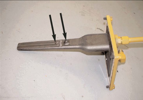
Coupling oil injector
Shown is the engine coupling oil injector. Oil flows through theorifices (arrows) and is sprayed on the spring coupling for lubrication and cooling

Engine spring coupling
Shown is the engine spring coupling installed in the front of the rear engine module. The spring coupling allows the crankshaft positions (timing) to be set. The engine module crankshafts are positioned (timed) with the front engine module at Top Dead Center (TDC) Compression and the rear engine module at TDC Exhaust.
Hydraulic Fan.
Shown is the 797B truck radiator module. The shunt tank can be seen on top of the radiator. The black hoses below the shunt tank provide a coolant supply to the jacket water and aftercooler water pumps. Most of the coolant flows to these two pumps from the radiator through the two large tubes at the bottom of the radiator. Coolant returns to the radiator through the large tubes in the radiator top tank. Coolant is supplied to the shunt tank from the radiator top tank through some small hoses below the shunt tank.The fan is hydraulically driven. A variable displacement piston-type pump provides oil flow to the fixed displacement motor shown in the center of the fan. The hydraulic motor turns the fan blades.
Fan speed is controlled by the Brake/Cooling ECM. Fan speed varies depending on many inputs but the maximum fan speed will be:
* 475 rpm--when not braking or retarding (going uphill)
* 525 rpm--when braking or retarding (going down hill)
The minimum fan speed will be 0 rpm; generally when all temperatures are cold
The inputs that determine fan speed are:
- Jacket water coolant temperature - Aftercooler coolant temperature
- Transmission lube temperature - Brake oil temperature
- Torque converter outlet temperature - Brake status
- Ground speed - Hoist system status output
When the hoist system is in the RAISE or LOWER position, the desired fan speed is reduced to 200 rpm to reduce the load on the pump drive.
Shown below are the fan speed limits based on the temperature sensor inputs, ground speed, and retarding/braking input.


After being programmed (flashed), the Brake/Cooling ECM needs to know what fan arrangement is installed on the machine. Because of the changes to the fan iron, there are three different configurations that the Brake/Cooling ECM has to support. They are listed below:
* 2438.4 mm ( 96 inch) fan with planetary drive
* 2692.4 mm (106 inch) fan with planetary drive
* 2692.4 mm (106 inch) fan with motor only
You must go through the following procedure when you first flash the software on the machine, and whenever the fan iron is updated (e.g. change from 96 to 106 inch fan, change fan control solenoid, . . .). In addition to these cases, if you replace the ECM, or flash an earlier version of software on the machine (e.g. 156-1394-10 or earlier), you will have to re-calibrate the machine.
This is the procedure to change the fan configuration:
1. Verify that Brake/Cooling ECM Software 188-9570-00 (or later) is installed on the machine.
2. Start ET and connect to the Brake/Cooling ECM.
3. Go to the "Service" menu. Under that menu, select the "Configuration" menu entry.
4. ET will display all of the configuration data for the Brake/Cooling ECM.
5. You will notice a parameter called "Fan w/PlanetaryDiam." Select this parameter using the mouse or arrow keys.
6. To change the value, either double click on the parameter, select the "Change" button in the lower left corner, or hit enter on the key board.
These are the allowed values for this parameter:
0 = fan with planetary is not installed
(e.g. new 2692.4mm (106inch) fan with motor only)
96 = fan with planetary is installed, diameter is 96 inches
(e.g. old 2438.4mm ( 96inch) fan with planetary drive)
106 = fan with planetary is installed, diameter is 106 inches
(e.g. new 2692.4mm (106inch) fan with old planetary drive)
7. Exit ET.
NOTE: The Brake/Cooling ECM will not allow you to change this parameter if the machine is moving.
This is the procedure to calibrate the fan:
1. Verify that Brake/Cooling ECM Software 188-9570-00 (or later) is installed on the machine.
2. Start ET and connect to the Brake/Cooling ECM.
3. Go to the "Service" menu.Under that menu, select the "Configuration" menu entry.
4. ET will display all of the configuration data for the Brake/Cooling ECM.
5. You will notice a parameter called "Fan Calibrate Start." Select this parameter using the mouse or arrow keys.
6. To change the value, either double click on the parameter, select the "Change" button in the lower left corner, or hit enter on the key board.
Enter a value of "1" to start the calibration process.
The Brake/Cooling ECM will refuse to start the calibration if ANY of the below cases are true:
a) Engine not running, or status unknown.
b) Machine moving, or status unknown.
c) Requested gear command unknown, or not NEUTRAL.
d) Actual gear unknown, or not NEUTRAL.
e) Engine throttle unknown.
f) Engine throttle above 5% limit.
g) Steering temperature unknown.
h) Steering temperature below 70°C (160°F) starting minimum limit.
i) Steering temperature above 110°C (230°F) calibrating maximum limit.
NOTE: If the user tries to trigger the calibration, and any of the above conditions are not met, then ET will return an error message that says "The value entered is not valid. The ECM has adjusted the value."
7. Wait for calibration to complete. At this time, the Brake/Cooling ECM will take over control of the throttle. At the same time, the Brake/Cooling ECM will turn the fan ON to calibrate the output.
You will know that the calibration is complete when the engine speed goes back to LOW IDLE.
Once the calibration has begun, it will stop if ANY of the below cases are true:
a) Engine not running, or status unknown.
b) Machine moving, or status unknown.
c) Requested gear command unknown, or not NEUTRAL.
d) Actual gear unknown, or not NEUTRAL.
e) Engine throttle unknown.
f) Engine throttle above 5% limit.
g) Steering temperature unknown.
h) Steering temperature below 65°C (150°F) calibrating minimum limit.
i) Steering temperature above 110°C (230°F) calibrating maximum limit.
j) Service tool request to stop the calibration received.
NOTE: The user may abort the calibration by changing any of the above conditions. Typically, this is done by depressing the throttle.
8. Check calibration error status.
After the engine speed is back at LOW IDLE, the user must refresh the configuration screen (hit the configuration icon again on ET, or select the "Service" - "Configuration" menu entry). The error status is contained in a parameter called "Fan Calibrate Error." The following is a list of the possible values:
"0" Calibration was successful.
"1" Calibration failed because conditions were not correct.
* This error could occur because the user aborted the test, or steering temperature dropped below 65°C (150°F), or . . .
"2" Calibration failed because fan did not stabilize.
* This error could occur because of a broken solenoid, a bad speed sensor, or . . .
9. Check fan response.
- This may be done by overriding the fan speed and verifying the response. The response should be checked to ensure that the fan reaches the top desired speed, and also that it does not overspeed.
10. Exit ET.
NOTE: Calibration will NOT be lost when you flash software in the Brake/Cooling ECM.

797B fan drive hydraulic system
Shown is the 797B fan drive hydraulic system. Oil flows from the fan drive pump through a makeup valve to the fan drive motor. Oil flows from the motor through the makeup valve and the steering/fan drive oil filters and cooler and returns to the steering/fan drive tank.If supply oil to the fan stops suddenly, the fan and motor may continue to rotate because of the mass of the fan. The makeup valve allows oil to flow from the return side of the circuit to the supply side to prevent a vacuum in the supply lines.
The fan drive motor is a fixed displacement motor, therefore, the fan speed is determined by the amount of flow from the fan drive pump. The fan drive pump is a variable displacement piston-type pump that is controlled by the Brake/Cooling ECM.
Case drain oil flows from the fan drive motor and pump through a case drain oil filter to the steering/fan drive tank
Steering supply oil flows from the steering solenoid and relief valve manifold to a pressure reducing valve. The pressure reducing valve reduces the steering pressure to a signal pressure of 6200 kPa (900 psi). Excess steering oil flows from the reducing valve back through the steering solenoid and relief valve manifold to tank. The reduced signal oil flows to the to the fan drive pump and the brake cooling drive pump.
The fan drive pump and the brake cooling drive pump use the signal oil pressure to destroke the pumps to minimum flow at start-up and during cold temperatures.

Fan drive motor.
Shown is closer view of the 797B fan drive motor. Oil flows from the fan drive pump through a makeup valve to the fan drive motor. Oil flows from the motor through the makeup valve and the steering/fan drive oil filter and returns to the steering/fan drive tank.The fan drive motor is a fixed displacement motor, therefore, the fan speed is determined by the amount of flow from the fan drive pump. The fan drive pump is a variable displacement piston-type pump that is controlled by the Brake/Cooling ECM.
Case drain oil flows from the fan drive motor through hose (1) and a case drain filter to the steering/fan drive tank.
The fan speed sensor (2) provides an input signal to the Brake/Cooling ECM. The Brake/Cooling ECM uses this input to maintain the fan speed between 0 and 525 rpm

Fan drive motor operation
Shown is a sectional view of the fixed displacement, bent-axis fan drive motor. The motor is rotated by flow from the fan drive pump. Oil flows through the supply port and the port plate and pushes the pistons out of the barrel. The pistons force the barrel and the output shaft to rotate. The output shaft turns the planetary drive group and the fan. As the barrel rotates and the pistons return, oil flows from the pistons through the port plate, the return port and a makeup valve to the steering/fan drive tank.Oil that leaks past the pistons into the motor housing provides lubrication for the rotating motor components. This oil leakage is referred to as case drain oil. Case drain oil flows through the case drain port and a case drain oil filter to the steering/fan drive tank.
The fan drive motor speed sensor provides an input signal to the Brake/Cooling ECM. The Brake/Cooling ECM uses this input to maintain the fan speed between 0 and 525 rpm.

Fan drive pump.
The fan drive pump (1) is part of a double piston pump group. The steering pump (2) is the other part of the pump group. The pump group is mounted on the front of the pump drive. The pump drive is located on the inside of the right frame rail near the torque converter. A charging pump is located between the steering pump and the fan drive pump and is used to keep the pumps supplied with oil. The fan drive pump is a variable displacement piston-type pump. The Brake/Cooling ECM controls the flow of oil from the fan drive pump by energizing the displacement solenoid (3).The Brake/Cooling ECM analyzes the temperatures, brake status, and ground speed inputs and sends between 0 and 680 milliamps to the solenoid. At 0 milliamps the pump is at maximum displacement and the fan speed is at maximum. At 680 milliamps the pump is at minimum displacement and the fan speed is at minimum. The coil resistance through the solenoid is approximately 24 ohms. The displacement solenoid moves a spool in the pressure and flow compensator valve (4) to control the flow of pump output pressure to the minimum angle actuator piston. The minimum angle actuator piston moves the swashplate to the minimum flow position. The current adjustment screw (5) controls the minimum current required to start destroking the pump.
NOTE: Do not adjust the current adjustment screw in chassis. This adjustment should only be done on a hydraulic test stand.
The high pressure cut-off valve (6) controls the maximum pressure in the fan drive system. The high pressure cut-off valve controls maximum pressure by controlling the flow of pump output pressure to the minimum angle actuator piston. When system pressure is at maximum, the high pressure cut-off valve sends oil to the minimum angle actuator piston and moves the swashplate to the minimum flow position. At sea level the high pressure cut-off valve setting is 22750 ± 345 kPa (3300 ± 50 psi).
NOTE: The high pressure cut-off valve setting must be set lower at higher altitudes. At 3142 Meters (10300 ft.) it only requires 15158 kPa (2200 psi) to maintain 525 rpm fan speed. If the fan drive pump solenoid is disconnected and the engine is run at high idle, the fan would overspeed if the high pressure cut-off valve setting is too high. A fan overspeed occurs at approximately 541 rpm.
When accelerating from LOW IDLE to HIGH IDLE, the fan drive pressure will spike to start the fan rotation. The spike pressure may be the pump high pressure cut-off setting. To adjust the pump high pressure cut- off setting, install a blocker plate in the pump outlet port and disconnect the fan drive pump solenoid. Start the engine and run at LOW IDLE.
The pump will destroke and operate at minimum flow and maximum pressure (High Pressure Cut-off). Adjust the high pressure cut-off to the specification.
The minimum angle stop screw (7) is located near the pressure and flow compensator valve. The maximum angle stop screw is located on the other side of the pump.
NOTE: Do not adjust the minimum or maximum angle stop screws in chassis. This adjustment should only be done on a hydraulic test stand.
A reducing valve (see Visual No. 147) provides a signal pressure through the hose (8) and a shuttle valve to the fan drive pump and the brake cooling drive pump.
At zero pressure, the actuator piston spring will hold the pump at maximum angle. The fan drive pump needs the signal pressure so that the displacement solenoid can position the fan drive pump at minimum angle at start-up and during cold temperatures. Without the signal pressure the pump could not stay at minimum angle to provide zero fan speed at start- up and during cold temperatures.

Fan drive and steering pump
Shown is a sectional view of the 797B fan drive pump. The fan drive pump is part of a double piston pump group. The steering pump is the other part of the pump group. The pumps are variable displacement piston-type pumps. Oil flows from the fan drive pump through a makeup valve to the fan motor. Fan speed is controlled by controlling the flow from the pump to the fan motor. Oil from the steering/fan drive tank enters the pump group in the port below the charge pump impeller. The charge pump keeps the two pumps full of oil.The large spring around the maximum angle actuator piston holds the swashplate at maximum angle. Pump output pressure is always present on the right side of the fan drive pump maximum angle actuator piston and also helps to hold the swashplate at maximum angle. When the swashplate is at maximum angle, pump output is at maximum flow and fan speed is at maximum. This is the position of the pump when the displacement solenoid receives 0 milliamps from the Brake/Cooling ECM.
When the displacement solenoid is receiving between 0 and 680 milliamps from the Brake/Cooling ECM, the displacement solenoid moves a spool in the pressure and flow compensator valve. The spool allows pump output pressure to flow to the minimum angle actuator piston.
The minimum angle actuator piston has a larger diameter than the maximum angle actuator piston. The minimum angle actuator piston moves the swashplate toward the minimum flow position. The swashplate angle, pump flow, and fan speed will modulate with the amount of current at the displacement solenoid. When the swashplate is at minimum angle, pump output is at minimum flow and fan speed is at minimum. This is the position of the pump when the displacement solenoid receives 680 milliamps from the Brake/Cooling ECM.
Before the swashplate contacts the minimum angle stop, the minimum angle actuator piston will open a small drain port to tank and stop the movement of the swashplate. Draining the minimum angle actuator piston oil will prevent the swashplate from contacting the minimum angle stop repeatedly which can be noisy and may cause damage to the pump.
Oil that leaks past the pistons into the pump housing provides lubrication for the rotating components. This oil leakage is referred to as case drain oil. Case drain oil flows through the case drain port and a case drain oil filter to the steering/fan drive tank.

Fan drive pump pressure and flow compensator valve.
Shown is the pressure and flow compensator valve for the 797B fan drive pump. The charge pump pulls oil from the steering/fan drive tank and keeps the steering and fan drive pumps full of oil. Oil flows from the pump to the high pressure cut-off valve, the displacement valve and the maximum angle actuator piston.The pump output oil and the spring around the maximum angle actuator piston holds the swashplate at maximum angle. This is the position of the pump when the displacement solenoid receives 0 milliamps from the Brake/Cooling ECM and pump output pressure is low.
When the displacement solenoid is receiving between 0 and 680 milliamps from the Brake/Cooling ECM, the displacement solenoid moves the valve spool to the left. The spool allows pump output pressure to flow to the minimum angle actuator piston. The minimum angle actuator piston has a larger diameter than the maximum angle actuator piston. The minimum angle actuator piston moves the swashplate toward the minimum flow position.
The current adjustment screw controls the spring pressure in the displacement valve and changes the minimum current required to start destroking the pump.
NOTE: Do not adjust the current adjustment screw in chassis. This adjustment should only be done on a hydraulic test stand.
The high pressure cut-off valve controls the maximum pressure in the fan drive system. The high pressure cut-off valve controls the flow of pump output pressure to the minimum angle actuator piston. When system pressure is at maximum, the high pressure cut-off valve sends oil to the minimum angle actuator piston and moves the swashplate to the minimum flow position. At sea level the high pressure cut-off valve setting is 22750 ± 345 kPa (3300 ± 50 psi).
NOTE: The high pressure cut-off valve setting must be set lower at higher altitudes. At 3142 Meters (10300 ft.) it only requires
15158 kPa (2200 psi) to maintain 525 rpm fan speed. If the fan drive pump solenoid is disconnected and the engine is run at high idle, the fan would overspeed if the high pressure cut-off valve setting is too high. A fan overspeed occurs at approximately 541 rpm.
When accelerating from LOW IDLE to HIGH IDLE, the fan drive pressure will spike to start the fan rotation. The spike pressure may be the pump high pressure cut-off setting.
To determine the correct high pressure cut-off setting at altitudes above sea level, use ET to override the hydraulic fan speed to 525 rpm, raise the engine speed to HIGH IDLE, and record the pump pressure and fan speeds. We now know what pressure is required to rotate the fan at
525 rpm at the current altitude. For example, at our current altitude, it required approximately 16675 kPa (2420 psi) to rotate the fan at 525 rpm. Pump cut-off pressure should be set a minimum of 2070 kPa (300 psi) above the pressure required to maintain the maximum fan speed
(525 rpm) with the solenoid unplugged. This will vary with the elevation above sea level. So, at this altitude we should set the pump cut-off pressure to a minimum of 18740 kPa (2720 psi).
To adjust the pump high pressure cut-off setting, install a blocker plate in the pump outlet port and disconnect the fan drive pump solenoid. Start the engine and run at LOW IDLE. The pump will destroke and operate at minimum flow and maximum pressure (High Pressure Cut-off). Adjust the high pressure cut-off to the specification

Steering oil supply hose.
Steering oil flows through the hose (1) to the pressure reducing valve (2). The pressure reducing valve reduces the steering pressure to a signal pressure of 6200 kPa (900 psi). Excess steering oil flows to tank through hose (3). The reduced signal oil flows through hose (4) to the to the fan drive pump and the brake cooling drive pump.The fan drive pump and the brake cooling drive pump use the signal oil pressure to destroke the pumps to minimum flow at start-up and during cold temperatures.

Fan drive makeup valve
Shown is the fan drive makeup valve (1). The makeup valve is located behind the lower right section of the radiator. Supply oil flows from the fan drive pump through the makeup valve to the fan drive motor. Return oil also flows from the fan drive motor through the makeup valve. Return oil from the fan motor is used as makeup oil to prevent a vacuum condition in the fan motor when the fan operation stops.If supply oil to the fan stops suddenly, the fan and motor may continue to rotate because of the mass of the fan. Continued rotation of the fan motor would create a vacuum in the supply circuit between the fan drive pump and motor. The makeup valve allows oil to flow from the return side of the circuit to the supply side and prevents a vacuum.
The fan drive pressure tap (2) is used to measure fan drive pump pressure. Pump pressure should be between 0 to 24115 kPa (0 to 3500 psi) at sea level. Pump pressure is adjusted at the high pressure cut-off valve mounted on the fan drive pump (see Visual No. 144). The pressure will vary depending on the desired fan speed set by the Brake/Cooling ECM

CONCLUSION
This presentation has provided basic maintenance information and described the systems operation of the electronic systems and engine for the 797B Off-highway Truck. All the major component locations were also identified. When used in conjunction with the service manual, the information in this package should permit the serviceman to analyze problems in any of the systems discussed on these trucks.
THANK YOU FOR YOUR VISITED
3524B ENGINE ON 797B OFF -HIGHWAY TRUCK
 Reviewed by heri
on
2:43 AM
Rating:
Reviewed by heri
on
2:43 AM
Rating:
Reviewed by heri
on
2:43 AM
Rating:


No comments: