

INTRODUCTION
This presentation provides an introduction to the Caterpillar 769D/771D/773D/775D Update Off-highway Trucks. Included in this package is a walk around inspection, which provides information about daily service requirements and identifies the locations of the major components. The major systems of the trucks will also be discussed. The major systems include the engine, power train, steering, hoist, and the air system and brakesThe load carrying capacity and Gross Machine Weights (GMW) of the "D" Series Update Trucks are:
769D: 36.8 metric tons (40.6 tons)
68182 kg (150000 lbs.) GMW
771D: 40.0 metric tons (44.1 tons)
73970 kg (163100 lbs.) GMW
773D: 52.3 metric tons (57.7 tons)
92530 kg (204000 lbs.) GMW
775D: 62.6 metric tons (69.1 tons)
106594 kg (235000 lbs.) GMW
Shown is the left side of a 775D update truck. The fuel tank is located on the left side of the truck. On the earlier "D" Series trucks, the fuel tank is located on the right side.

Brake system components located on right platform.
Shown is the right side of a 775D update truck. The service and retarder air tanks, the brake master cylinders, the relay valves and the brake oil makeup tank are located on the right platform near the steering tank and the engine air filters.The main hydraulic tank is also visible. The hydraulic tank supplies oil for the hoist system and the brake system.
On the earlier "D" Series trucks, torque converter oil is also supplied from the main hydraulic tank. A transmission oil supply tank is located in front of the main hydraulic tank.
The "D" Series update trucks use the torque converter case as the supply tank for the torque converter and the transmission.
The muffler is located in front of the hydraulic tank.

775D update truck.
Shown is the front of a 775D update truck. The 773D and 775D update trucks are equipped with a conventional radiator core. All other Caterpillar Off-highway Trucks use a folded core radiator.The folded core radiator provides the convenience of repairing or replacing smaller individual cores. The conventional radiator requires repair or replacement of a large single core.

Truck body options.
Shown is the rear of a 771D update truck. Two body options are available for the "D" Series update trucks:* A 12 degree flat floor design that provides uniform load dumping, excellent load retention and a low center of gravity.
* A dual slope design with a "V" bottom main floor to reduce shock loading, center the load and reduce spills.
All internal wear surfaces of the truck bodies are made with 400 Brinell hardness steel. All attachment body liners are also made with 400 Brinell hardness steel. The external components of the bodies are made of steel with a yield strength of 6205 bar (90000 psi).
The rear suspension cylinders absorb bending and twisting stresses rather than transmitting them to the main frame.

WALK AROUND INSPECTION.
Before working on or operating the truck, read the Operation and Maintenance Manual thoroughly for information on safety, maintenance and operating techniques.Safety Precautions and Warnings are provided in the manual and on the truck. Be sure to identify and understand all symbols before starting the truck.
The first step to perform when approaching the truck is to make a thorough walk around inspection. Look around and under the truck for loose or missing bolts, trash build-up and for coolant, fuel or oil leaks. Look for indications of cracks. Pay close attention to high stress areas as shown in the Operation and Maintenance Manual.

Maintenance
The following list identifies the items that must be serviced every 10 Hours or Daily.- Walk around inspection: Check for loose or missing bolts, leaks and cracks in frame structures
- Suspension cylinders: Measure/recharge
- Primary fuel filter/water separator: Drain moisture
- Transmission and torque converter oil: Check level
- Hoist and brake cooling oil: Check level
- Rear axle breather: Check for plugging
- Fuel tank: Drain moisture
- Radiator: Check level and radiator core plugging
- Steering system oil: Check level
- Air tanks: Drain moisture
- Engine crankcase oil: Check level
- Brakes: Check operation
- Indicators and gauges: Test operation
- Seat belt: Inspect
- Back-up alarm: Test operation
- Secondary steering: Test operation

Front wheel bearing inspection plug (arrow)
The front wheel bearing oil level is checked and filled by removing the plug (arrow) in the center of the wheel bearing cover. The oil should be level with the bottom of the plug hole.The service interval for changing the front wheel bearing oil has been reduced from 2000 hours to 500 hours.
Use only Transmission Drive Train Oil (TDTO) with a specification of TO-4 or newer. TDTO TO-4 provides increased lubrication capability for bearings.
Check the tire inflation pressure. Operating the truck with the wrong tire inflation pressure can cause heat build-up in the tire and accelerate tire wear.
NOTE: Care must be taken to ensure that fluids are contained while performing any inspection, maintenance, testing, adjusting and repair of the machine. Be prepared to collect the fluid in suitable containers before opening any compartment or disassembling any component containing fluids. Refer to the "Tools and Shop Products Guide" (Form NENG2500) for tools and supplies suitable to collect and contain fluids in Caterpillar machines. Dispose of fluids according to local regulations and mandates

Front suspension cylinder charge
Check the front suspension cylinders for leaks or structural damage. Check the charge condition of the front suspension cylinders when the truck is empty and on level ground. Measure the charge height of the suspension cylinders and compare the dimension with the dimension that was recorded the last time the cylinders were charged. Recharge the cylinders with oil and nitrogen if necessary.A grease outlet fitting is located on one side of each front suspension cylinder. The grease supply fitting (arrow) is located on the opposite side of the suspension cylinder. No grease outlet fittings should be located on the same side of the suspension cylinder as the grease fill location. An outlet fitting positioned on the same side of the suspension cylinder as the grease fill location will prevent proper lubrication of the cylinder.
Make sure that grease is flowing from the outlet fittings to verify that the suspension cylinders are being lubricated and that the pressure in the cylinders is not excessiv
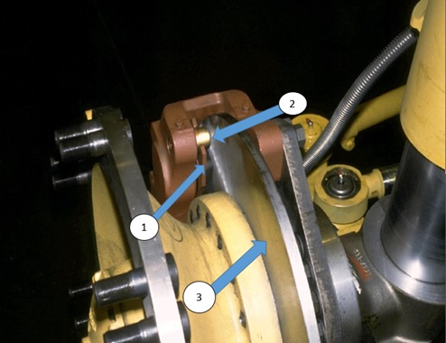
Brake linings.
Inspect the brake linings (1) for wear. The brake linings (not including the carrier) must be a minimum of 3.15 mm (.125 in.) thick. Measure the lining at both ends because one end can wear more than the other.The clearance between the brake carrier guide pins (2) and the brake disc (3) must be a minimum of 1.5 ± 0.5 mm (.06 ± .02 in.).

3408E engine
Shown is a 3408E engine used in the 769D and 771D update trucks. Located on the right side of the engine are the primary fuel filter (1) and the secondary fuel filter (2).A fuel priming pump (3) is located on top of the primary fuel filter. The fuel priming pump is used to fill the filters after they are changed.
A water separator cup is located on the bottom of the primary fuel filter. Condensation should be drained daily from the water separator cup through the drain valve (4).
Engine oil samples can be taken from the Scheduled Oil Sampling (S•O•S) tap (5).
An S•O•S coolant analysis tap (6) is located near the water pump on the "D" Series Update Truck engines.
NOTE: If the fuel system requires priming, it may be necessary to block the fuel return line during priming to force the fuel into the injectors

3412E engine
Shown is a 3412E engine used in the 773D and 775D update trucks. Located on the right side of the engine are the primary fuel filter (1), the two secondary fuel filters (2) and the two engine oil filters (3).A fuel priming pump (4) is located on top of the primary fuel filter. The fuel priming pump is used to fill the filters after they are changed.
A water separator cup is located on the bottom of the primary fuel filter. Condensation should be drained daily from the water separator cup through the drain valve (5).
Engine oil samples can be taken from the Scheduled Oil Sampling (S•O•S) tap (6).
NOTE: If the fuel system requires priming, it may be necessary to block the fuel return line during priming to force the fuel into the injectors.

Air dryer
The air dryer (1) is located behind the right front suspension cylinder. Inspect for oil spray around the air dryer. Oil spray can indicate that a problem exists in the air compressor.Steering system oil samples can be taken from the Scheduled Oil Sampling (S•O•S) tap (2) located in the steering return hose.

Transmission and torque converter oil level sight gauges.
Supply oil for the transmission and the torque converter is contained in the torque converter case.Sight gauges (1) are used to check the oil level for the transmission and the torque converter.
Transmission and torque converter oil is added at the fill tube (2). When filling the transmission and torque converter oil sump after an oilchange, fill the sump with oil to the top of the upper sight gauge. Crank
the engine for approximately 15 seconds. The oil level will decrease as oil fills the transmission and torque converter system. If the engine starts, do not allow it to run for more than 15 seconds. Add more oil to the sump to raise the oil level to the FULL COLD mark. Crank the engine for an additional 15 seconds. Repeat this step as required until the oil level stabilizes.
Start the engine and warm the transmission and torque converter oil. Add more oil to the sump as required to raise the transmission and torque converter oil level to the FULL WARM mark with the engine running.
Use only Transmission Drive Train Oil (TDTO) with a specification of TO-4 or newer.
* TDTO TO-4 oil provides maximum frictional capability required for clutch discs used in transmissions and torque converters.
* TDTO-4 oil increases rimpull because of reduced slippage.
* Use only mono-viscosity (straight weight) oils. Multi-viscosity oils use viscosity improvers which, when subjected to shearing conditions, are reduced to the lower weight rating. For example, when a 10W-30 oil is used in a shear condition, after time the oil will only perform to 10W specifications.
* Never use engine oil in transmissions. Engine oils are formulated to minimize friction. Oils used in transmissions and torque converters must allow adequate friction to reduce slippage.
NOTICE
Failure to correctly fill the transmission and torque converter oil sump after an oil change may cause transmission clutch damage.

Hoist and brake hydraulic tank
Shown is the hoist and brake hydraulic tank. The oil level is checked by opening the small door (1) and looking through the sight gauge. The oil level should first be checked with cold oil and the engine stopped. The level should again be checked with warm oil and the engine running.The lower sight gauge (2) is used to fill the tank when the hoist cylinders are in the RAISED position. When the hoist cylinders are lowered, the hydraulic oil level will increase. After the hoist cylinders are lowered, check the hydraulic tank oil level with the upper sight gauge.
Use only Transmission Drive Train Oil (TDTO) with a specification of TO-4 or newer. TDTO TO-4 oil:
* Provides maximum frictional capability required for the clutch discs used in the brakes.
* Increases brake holding capability by reducing brake slippage.
* Minimizes brake chatter.
Check the hoist and brake hydraulic tank breather (3) for plugging (cover removed for visibility). Clean the filter if plugged.
Brake cooling oil returns to the hydraulic tank through a screen located inside the tank behind the return tube (4).
The diverter (towing) valve (5) is used to release the parking brakes if towing with a dead engine is necessary. The towing valve will be discussed in more detail in the Air System and Brakes section of this presentation.

Final drives
The rear axles are equipped with planetary-type final drives. The magnetic plug (arrow) should be removed from the final drives at regular intervals and checked for metal particles. For some conditions, checking the magnetic plug is the only way to identify a problem which may exist.Use only Transmission Drive Train Oil (TDTO) with a specification of TO-4 or newer. TDTO TO-4 oil provides:
* Maximum frictional capability required for gears.
* Increased lubrication capability for bearings.
NOTICE
The rear axle is a common sump for the differential and both final drives. If a final drive or the differential fails, the other final drive components must also be checked for contamination and then flushed. Failure to completely flush the rear axle after a failure can cause a repeat failure within a short time.

Differential oil level plug.
Check the differential oil level by removing the fill plug (1). The oil should be level with the bottom of the fill plug opening.Inspect the rear suspension cylinders for leaks or structural damage. Check the charge condition of the rear suspension cylinders when the truck is empty and on level ground. Measure the charge height of the suspension cylinders, and compare the dimension with the dimension that was recorded the last time the cylinders were charged. Recharge the cylinders if necessary.
Inspect the condition of the rear axle breather (2) at regular intervals. The breather prevents pressure from building up in the axle housing. Excessive pressure in the axle housing can cause brake cooling oil to leak through the Duo-Cone seals in the wheel brake assemblies.

The body up retaining pins (arrow) are stored below the rear of the body. When work is to be performed while the body is raised, the body up retaining pins must be installed through the pin holes in the body and the rear frame to hold the body in the raised position.
WARNING
The space between the body and the frame becomes a zero clearance area when the body is lowered. Failure to install the body up pins can result in injury or death to personnel working in this area.

Fuel tank
The fuel tank is located on the left side of the truck. The fuel level sight gauge (1) is used to check the fuel level during the walk around inspection.A fuel level sender is located on the fuel level sight gauge. The fuel level sender provides input signals to the Caterpillar Monitoring System, which informs the operator of the fuel level.
The percentage of sulfur in the fuel will affect the engine oil recommendations. The following is a summary of fuel sulfur and oil recommendations:
* Use API CH-4 performance oils.
* With fuel sulfur below 0.5%, any API CH-4 oils will have a sufficient Total Base Number (TBN) for acid neutralization.
* For fuel sulfur values above 0.5%, the new oil TBN should be a minimum of 10 times the fuel sulfur.
* When 10 times the fuel sulfur exceeds the oil TBN, reduce the oil change interval to approximately 1/2 the normal change interval.
Open the drain valve (2) to remove condensation from the fuel tank.

Transmission and torque converter filters
Located in front of the fuel tank are the transmission and torque converter filters (1). Oil flows from the transmission and torque converter charging pump through the transmission and torque converter filters to the transmission control valves on top of the transmission and to the torque converter lockup clutch valve located on top of the torque converter.Transmission and torque converter oil samples can be taken at the Scheduled Oil Sampling (S•O•S) tap (2).
A transmission and torque converter filter bypass switch (3) is located on the filter base. The bypass switch provides input signals to the Caterpillar Monitoring System, which informs the operator if the transmission and torque converter filters are restricted.
Shown is a 769D/771D update truck. On these trucks, the secondary steering/towing, engine prelube and starter relays are mounted outside the frame near the top of the left suspension cylinder. On 773D/775D update trucks, the secondary steering/towing and engine prelube relays are mounted on each side of the parking brake filters.

Parking brake release filter
The parking brake release filters (1) are located inside the left frame in the engine compartment. Oil flows from the parking brake release pump through the parking brake release filters, to the parking brake release valve.Parking brake release supply oil also flows to the hoist control valve and is used as pilot oil to shift the hoist directional spool.
Hoist and brake oil samples can be taken at the Scheduled Oil Sampling (S•O•S) tap (2).
Shown is a 773D/775D update truck. On these trucks, the secondary steering/towing and engine prelube relays are mounted on each side of the parking brake filters. On 769D/771D update trucks, these relays are mounted outside the frame near the top of the left suspension cylinde.

Auxiliary starting receptacle
Shown is the left side engine compartment in a 775D update truck. If necessary, the auxiliary starting receptacle (1) can be used to connect battery jumper cables.If the truck is equipped with the attachment quick service oil change system, engine oil can be added through the high speed oil change connector (2).
If jump starting the vehicle is necessary, proper safety precautions must be followed to avoid personal injury or to prevent damaging the electrical system of the starting vehicle or the one being jump started. Before jump starting the machine, be sure to read and understand the warnings on the machine and in the Operation and Maintenance Manual.

3408E engine oil filter.
Shown is a 3408E engine used in the 769D and 771D update trucks. The engine oil filters are located on the left side of the engine.
Inspect radiator
While climbing the ladder, make a thorough inspection of the radiator. Be sure that no debris or dirt is trapped in the radiator cores.The battery disconnect switch (arrow) is located behind a cover near the right access ladder. If the machine is being parked for an extended period (overnight, etc.), turn off the disconnect switch and remove the key.
NOTICE
Never turn the disconnect switch off with the engine running. Damage to the engine charging system could result.

Coolant level sight glass (not shown)
The engine coolant level is checked with a coolant level sight glass (not shown) located on the right side of the radiator top tank. Coolant is added by removing the radiator cap (1).The water used in the cooling system is critical for good cooling system performance. Use distilled or deionized water whenever possible to prevent acids or scale deposits in the cooling system. Acids and scale deposits result from contaminants that are found in most common water sources.
Never use water alone. All water is corrosive at engine operating temperatures without supplemental coolant additives. Also, water alone has none of the lubrication properties which are required for water pump seals.
The "D" Series trucks are filled at the factory with Extended Life Coolant (ELC). If ELC is maintained in the radiator, the use of a supplemental coolant additive is not necessary. If more than 10% of conventional coolant is mixed with the ELC, a supplemental coolant additive is required..
With conventional coolant, maintain a 3 to 6% concentration of supplemental coolant additive.
• Too much additive will form insoluble salts that cause water pump seal wear, plugging and will coat parts with excessive deposits that prevent heat transfer.
• Not enough additive will result in severe cavitation erosion which will pit and corrode cylinder liner and block surfaces.
• To prevent an over concentration of inhibitor, never use both the liquid supplemental coolant additive and the supplemental coolant additive element at the same time.
• Use the 4C9301 Test Kit to measure the concentration of the supplemental coolant additive in the cooling system.
Maintain a 30 to 60% concentration of Caterpillar Antifreeze.
• More than 60% antifreeze concentration will reduce freeze protection and cause radiator plugging.
• Less than 30% antifreeze concentration will result in cavitation erosion, which will pit and corrode cylinder liner and block surfaces and decrease water pump life.
• Most commercial antifreezes are formulated with high silicate content for gasoline engines and are not recommended for diesel engines.
The engine should operate between 88 and 99°C (190 and 210°F).
• Operating below this temperature range will cause overcooling problems.
• Operating above this temperature range will cause overheating problems.
Cooling system pressure should be between 55 and 110 kPa (8 and 16 psi).
• Raising the pressure raises the boiling point. If the pressure is inadequate, the coolant will boil over and the engine will overheat.
Do not fill the cooling system faster than 20 L/min (5 gpm).
Filling the cooling system faster than 20 L/min (5 gpm) will cause air pockets that could produce damaging steam.
Keep the fan belts adjusted.
Keep the radiator cooling fins straight and clean.
If the truck is equipped with an ether start system, the engine ECM will automatically inject ether from the ether cylinder (2) during cranking. The operator can also inject ether manually with the start aid switch in the cab (see Slides No. 35 and 62).
The engine ECM will energize the ether injection relay only if:
• Engine oil temperature is below 10°C (50°F).
• Coolant temperature is below 10°C (50°F)--back-up for oil temperature.
• Engine speed is below 1200 rpm.
NOTE: The manual start aid switch is a dealer installed option

Batteries
The batteries are below the access panel on the right platform. Inspect the battery connections for corrosion or damage. Keep the battery terminals clean and coated with petroleum jelly.Inspect the electrolyte level in each battery cell, except for maintenance free batteries. Maintain the level to the bottom of the fill openings with distilled water.
WARNING
Batteries give off flammable fumes that can explode resulting in personal injury.
Prevent sparks near batteries. They could cause vapors to explode. Do not allow jump cable ends to contact each other or the machine.
Do not smoke when checking battery electrolyte levels. Electrolyte is an acid and can cause personal injury if it contacts skin or eyes.
Always wear eye protection when starting a machine with jumper cables.
Always connect the battery positive (+) to battery positive (+) and the battery negative (-) to stalled machine frame (-).

Engine air intake system components
Shown are the air intake system components. Located above the air filter housings are the precleaner bowls (1). Check the level of dirt accumulation in the precleaner bowls. Empty the precleaner bowls when the dirt level reaches the full mark.Service the air filters when the air filter restriction indicator located on the dash (see Slide No. 36) illuminates or when black exhaust smoke occcurs. The alert indicator lights when the filter restriction is approximately 7.5 kPa (30 in. of water).
Two filter elements are installed in the filter housings. The large element is the primary element (2) and the small element is the secondary element (3).
Air intake system tips:
• The primary element can be cleaned a maximum of six times.
• Never clean the secondary element for reuse. Always replace the secondary element.
• Air filter restriction causes black exhaust smoke and low power.
• A 0.6°C (1°F) increase in intake temperature increases exhaust temperature 1.8°C (3°F).
• For every 250 mm (10 in.) of water restriction above 500 mm (20 in.) of water in an air filter, the inlet temperature increases 60°C (100°F).
• Exhaust temperature should not exceed 650°C (1200°F).

Steering system tank
Located behind the air filters is the steering system tank. Check the steering system oil level at the sight gauge (1).The steering system oil filter (2) is located on the side of the steering tank.
The steering system uses a pressure compensated piston-type pump. Case drain oil from the steering pump returns to the hydraulic tank through a screen that is part of the fitting (3) installed in the side of the steering tank.
Before removing the cap to add oil to the steering system, depress the pressure release button (4) on the breather to release any remaining pressure from the tank.
The service and retarder brake air tanks are located behind the steering tank. Drain condensation from the tanks daily with the drain valve (5)

Brake master cylinders
Located near the air filters and the steering tank are the front and rear brake cylinders (1) and the brake oil makeup tank (2).Inspect the condition of the breathers (3) for the brake cylinders. Oil should not leak from the breathers. Oil leaking from the breathers indicates that the oil piston seals in the brake cylinder need replacement. Air flow from the breathers during a brake application indicates that the brake cylinder air piston seals need replacement.
If air is in the system or a loss of oil downstream from the cylinders occurs, the piston in the cylinder will overstroke and cause an indicator rod to extend and open the brake overstroke switch (4). The switch provides an input signal to the Caterpillar Monitoring System, which informs the operator of the condition of the service/retarder brake oil circuit. If an overstroke condition occurs, the problem must be repaired and the indicator rod pushed in to cancel the warning.

Engine oil level dipstick
Check the engine oil level with the dipstick (1) and add engine oil at the fill tube (2).Use only Diesel Engine Oil (DEO) with a specification of CF-4 or newer. DEO oil with a CH-4 specification is available and should be used if possible. CH-4 engine oil:
• Requires more performance tests than previous oils, such as CE or CF, and has a narrower performance band.
• Can withstand higher temperatures before coking and has better dispersing capability for controlling soot.
• Has better fuel sulfur neutralization capability.
Check the fluid level of the windshield washer reservoir (3).
Another small air tank (not visible) is located behind the cab
(see Slide No. 142). The air tank behind the cab supplies air to the parking and secondary brakes. Drain the moisture from the tank daily with the drain valve (4).
NOTE: Check the level of all oil compartments again with the engine running after the oil reaches the normal operating temperature.

10 hours/daily checks performed in the operator's cab
The remaining 10 Hours or Daily checks are performed in the operator's compartment:• Brakes: Check operation
• Indicators and gauges: Test operation
• Seat belt: Inspect
• Back-up alarm: Test operation
• Secondary steering: Test operation
The brakes are checked by engaging one of the brake systems and placing the shift lever in FIRST FORWARD. Accelerate the engine until the truck moves. The truck must not move below 1200 rpm. This procedure should be repeated for each brake lever or pedal.
The cab fresh air filter is located behind the cover in the right front corner of the cab. Clean or replace the cab fresh air filter when necessary.
THANK YOU FOR YOUR VISITED
INTRODUCTION 775D OFF-HIGHWAY TRUCK
 Reviewed by heri
on
1:48 PM
Rating:
Reviewed by heri
on
1:48 PM
Rating:
Reviewed by heri
on
1:48 PM
Rating:


No comments: