
OPERATOR STATION 777D OFF-HIGHWAY TRUCK

OPERATOR'S STATION
The operator's station for the 777D Update Off-highway Trucks has been changed to improve operator comfort and ergonomics. The 777D Update cab now resembles the cab used on the smaller "D" Series Off-highway Trucks.The Truck Production Management System (TPMS) on the 777D Update Trucks is controlled by a separate ECM and is not on the Cat Data Link. There are two sets of TPMS external loading lamps on the truck. One set of lamps is on the left side of the cab (arrow) and the other set is on the right platform. The lamps are green and red. The lamps inform the loader operator of the loading progress toward a target payload weight. The lamps are active only during the loading cycle and are off at all other times.
During loading, the green (continue loading) lamps will be ON until the payload is 95% of the target weight setting. Then, the red (stop loading) lamp will light. A "last pass" indication can be programmed into the system. With last pass indication, the TPMS calculates an average loader pass size and predicts payload weight. If the predicted weight after the NEXT loader pass will be above 95% of the target weight setting, the red lamps FLASH. The red lamps will be ON continuously after the last pass (when fully loaded). A minimum of three loader passes are required for the "last pass" indication option to function correctly.

Operator and trainer seats
Shown is a view of the operator's seat and the trainer's seat. The seats are more comfortable with improved seat adjustments.
Front panel components
Machine ControlsLocated on the left side of the front panel are:
- Telescopic/tilt steering column adjustment lever (1): Push for telescoping and pull for tilt.
- Intermittent wiper/washer, turn signal control and dimmer switch (2)
- Steering wheel mounted electric horn control (3)
- Cigarette lighter (4): The cigarette lighter socket receives a 24-Volt power supply. This socket can be used as a power supply for 24-Volt appliances. A 12-Volt power port is provided behind the operator's seat.
- Front brake ON/OFF switch (5): (caliper disc front brakes only) When this switch is in the OFF position, the front brakes will NOT ENGAGE when the operator uses the service brake pedal.

Windshield washer
Shown is a closer view of the intermittent wiper/washer, turn signal control and dimmer switchWindshield washer: Push the button at the end of the lever to activate the electrically powered windshield washer.
Intermittent wiper switch (six positions):
- OFF (0)
- Intermittent position 1 (one bar)
- Intermittent position 2 (two bars)
- Intermittent position 3 (three bars)
- Low speed continuous wiper (I)
- High speed continuous wiper (II)
Dimmer switch: Pull the lever toward the operator for BRIGHT lights, and push the lever away from the operator for DIM lights.
Turn signals: Lift the lever for a RIGHT turn, and lower the lever for a LEFT turn.
A power window switch is mounted on the door as seen to the left of the steering wheel

Retarder lever (black):
Located on the right side of the steering column is the retarder lever (black). The retarder lever is used to modulate engagement of the service brakes. The retarder lever engages only the rear brakes on trucks with caliper disc front brakes, but engages the front and rear brakes on trucks with the optional oil cooled front brakes. The retarder lever can control the modulation of the service brakes more precisely than the service brake pedal located on the cab floor.Located on the dash to the right of the retarder lever are (from left to right):
- Key start switch
- Temperature variable knob
- Fan speed switch
NOTE: When the key start switch is turned to the crank position, if the Caterpillar Pre-Lubrication System is installed, a "P" will appear on the Caterpillar Monitoring System display during pre-lubrication.
During engine cranking, if the ether starting aid is installed, an "E" will appear on the display during ether injection

The top gear limit and body up gear limit are programmable through the Transmission/Chassis ECM. The top gear limit can be changed from THIRD to SEVENTH. The body up gear limit can be changed from FIRST to THIRD.
On the floor is the throttle pedal (3). A throttle position sensor (4) is attached to the throttle pedal. This sensor provides the throttle position input signals to the Engine ECM.
The throttle position sensor receives a regulated 8.0 ± 0.5 Volts from the Engine ECM. The duty cycle output of the throttle position sensor should be 16 ± 6% at LOW IDLE and 85 ± 4% at HIGH IDLE.
The Engine ECM provides an elevated engine idle speed of 1300 rpm when the engine coolant temperature is below 60°C (140°F). The rpm is gradually reduced to 1000 rpm between 60°C (140°F) and 71°C (160°F). When the temperature is above 71°C (160°F), the engine will idle at LOW IDLE (700 rpm).
Increasing the low idle speed helps prevent incomplete combustion and overcooling. To temporarily reduce the elevated idle speed, the operator can release the parking brake or depress the throttle momentarily, and the idle speed will decrease to LOW IDLE for 10 minutes.

Secondary brake pedal
Located on the floor of the cab are* Secondary brake pedal (1): Used to modulate application of the parking brakes on the rear wheels and the service brakes on the front wheels.
* Service brake pedal (2): The service brake pedal is used to modulate engagement of the service brakes on all four wheels if the front brake ON/OFF switch is in the ON position (see Slide No. 35). For more precise modulation of the service brakes, use the manual retarder lever on the right side of the steering column.
* Throttle pedal (3): A throttle position sensor is attached to the throttle pedal. The throttle position sensor provides the throttle position input signals to the Engine ECM

Hoist control lever (arrow)
The 777D Update truck hoist system is electronically controlled. The hoist control lever (arrow) activates the four positions of the hoist control valve. The four positions are: RAISE, HOLD, FLOAT and LOWER.A fifth position of the hoist valve is called the SNUB position. The operator does not have control over the SNUB position. The body up switch (see Slide No. 132) controls the SNUB position of the hoist valve. When the body is lowered, just before the body contacts the frame, the Transmission/Chassis ECM signals the hoist solenoids to move the hoist valve spool to the SNUB position. In the SNUB position, the body float speed is reduced to prevent hard contact of the body with the frame.
The truck should normally be operated with the hoist lever in the FLOAT position. Traveling with the hoist in the FLOAT position will make sure the weight of the body is on the frame and body pads and not on the hoist cylinders. The hoist valve will actually be in the SNUB position.
If the transmission is in REVERSE when the body is being raised, the hoist lever sensor is used to shift the transmission to NEUTRAL. The transmission will remain in NEUTRAL until:
1. The hoist lever is moved into the HOLD or FLOAT position; and
2. the shift lever has been cycled into and out of NEUTRAL. The hoist lever is also used to start a new TPMS cycle.
NOTE: If the truck is started with the body raised and the hoist lever in FLOAT, the lever must be moved into HOLD and then FLOAT before the body will lower.

Caterpillar Monitoring System
The Caterpillar Monitoring System is a flexible, modular monitoring system that includes: a message center module, various switches and sensors, an action lamp and action alarm.The "heart" of the system is the message center module where information is received from switches and sensors over the CAT Data Link and processed. The message center module then activates various output components.
The Truck Payload Measurement System (TPMS) is an optional system that can be installed on the trucks to monitor and record production data such as payloads and cycle times. The TPMS is not on the CAT Data Link and requires a separate communication port for downloading and viewing the production information.

Caterpillar Monitoring System
The Caterpillar Monitoring System includes: a four-gauge cluster module, a speedometer/tachometer module, a message center module, an action lamp and an action alarm. The message center module receives information from switches, sensors and other electronic controls on the machine through the CAT Data Link. The message center module processes this information and activates various output components. The output components could be in the four-gauge cluster module, the speedometer/tachometer module, the alert indicator or display window of the message center module, the action lamp and the action alarm. The display window shows the operator the condition of the machine systems and system diagnostic information.The system has three Warning Categories. Category 1 alerts the operator of an abnormal machine condition by a gauge in the red zone and/or a flashing alert indicator. A Category 2 Warning will cause the action lamp to light in addition to the message center alert indicator. A Category 2 warning indicates that immediate operator action is necessary. Category 3 adds an action alarm, indicating that immediate machine shutdown is necessary.

Caterpillar Monitoring System
* Inputs
* Outputs
Shown is a diagram of the Caterpillar Monitoring System. Shown on the left are the components on the machine that provide inputs directly to the Message Center Module. The Message Center Module analyzes these inputs along with the inputs from the other ECM’s and sends output signals to the components shown on the right side of the diagram.
The harness code consists of five pins in the Message Center Module 40-pin connector that can be either OPEN or GROUNDED. The combination of OPEN or GROUNDED pins determines which machine parameters the Message Center Module will perform. For example, if pins 3 and 12 are GROUNDED and pins 6, 16 and 22 are OPEN, that Message Center Module will function as a 777D Update Off-highway Truck. When connecting a laptop with ET software, ET will also automatically show this as a 777D Update Off-highway Truck

Center front dash panel
Shown is the center of the front dash panel. Nine dash indicators, the four-gauge cluster module and the speedometer/tachometer module are visible.
The four dash indicators to the left of the four-gauge cluster module are (from top to bottom):
* Left turn
* Body up: Lights when the body is up. Input is from the body up switch.
* Reverse: Lights when the shift lever switch is in REVERSE.
* High beam
Right dash indicators (top to bottom
The five dash indicators to the right of the speedometer/tachometer module are (from top to bottom):
* Right turn
* Action lamp: Lights when a Category 2 or Category 3 Warning is active.
* Secondary Steering: Lights when the secondary steering pump is ON.
* Retarder: Lights when the retarder is ENGAGED (Auto or Manual). Flashes rapidly if a fault in the ARC system is detected.
* TCS: Lights when the Traction Control System (TCS) is ENGAGED. Flashes rapidly if a fault in the TCS system is detected or when performing the TCS test.
The four parameters monitored by the four-gauge cluster module are (top then bottom, left to right):
* Engine coolant temperature: Maximum operating temperature is 107°C (225°F).
* Brake oil temperature: Maximum operating temperature is 124°C (255°F).
* System Air Pressure: Minimum operating pressure is 483 kPa (70 psi).
* Fuel Level: Minimum operating level is 8%.
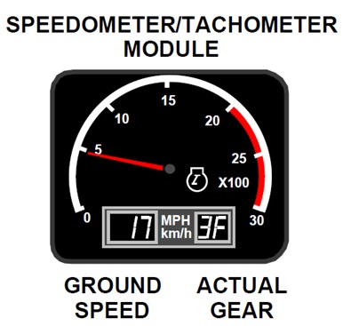
Speed/tachometer module
The three parameters monitored by the speedometer/tachometer module are:* Tachometer: Displays the engine speed in rpm.
* Ground speed: Displayed in the left side of the three-digit display area and can be displayed in miles per hour (mph) or kilometers per hour (km/h).
* Actual gear: Displayed in the right side of the two-digit display area and consists of two digits that show the actual transmission gear that is engaged. The left digit shows the actual gear (such as "1," "2," etc.). The right digit shows the direction selected ("F," "N" or "R").

Rocker switches (top row):
To the right of the speedometer/tachometer module are several rocker switches. The rocker switches control the following parameters:Top row (from left to right):
* Lights
* Vacant
* ARC: Activates the Automatic Retarder Control (ARC) system.
* TCS test: Tests the Traction Control System (TCS). Use this switch when turning in a tight circle with the engine at LOW IDLE and the transmission in FIRST GEAR. The brakes should ENGAGE and RELEASE repeatedly. The test must be performed while turning in both directions to complete the test.
* Caterpillar Monitoring System operator scroll: Allows the operator to scroll through the Operator Modes in the message center module display window (see Slide No. 49).
Bottom row (from left to right):
* Throttle back-up/throttle lock (customer installed option): Throttle back-up: Raises the engine speed to 1300 rpm if the throttle sensor signal is invalid.
Throttle lock: If the transmission is in NEUTRAL and the parking brake is ENGAGED, the throttle lock will hold any current engine rpm selected by the operator. If any service or retarder brake is ENGAGED, the engine rpm will return to LOW IDLE. After a brake application, the throttle lock must be turned OFF to reset the system before the throttle lock function will work again.
* Ether starting aid (customer installed option): Allows the operator to manually inject ether if the engine oil temperature is below 10°C (50°F) and engine speed is below 1900 rpm .
* Air conditioning
* Body up sound reduction: Reduces the engine HIGH IDLE to 1800 rpm when the body is RAISED
* Secondary steering and parking brake release: Normally, when this switch is depressed, the steering system receives secondary steering oil and parking brake release oil flows to the tank. When the brake release diverter (towing) valve spool is shifted, this switch will also release the parking brakes.
NOTE: The secondary steering and parking brake release switch can also be used to provide hoist pilot oil for lowering the body on trucks with an inoperable engine

Message center module
To the right of the rocker switches is the message center module. The message center module contains ten alert indicators and a message display window.The alert indicators on the message center module represent the following parameters:
Top row (from left to right):
* Engine oil pressure: The minimum operating pressure at low idle is 44 kPa (6.4 psi) and at high idle is 172 kPa (25 psi).
* Parking brake ON or rear brake master cylinder overstroke.
* Torque converter oil temperature or brake oil temperature: The maximum operating temperature is 124°C (255°F).
* Battery charging: A Category 1 Warning is generated if the voltage on the message center Pin No. 1 is less than 23.8 or greater than 28.5 Volts. A Category 3 Warning is generated if the voltage is less than 22 or greater than 31 Volts. The minimum "R" terminal frequency is 90 Hz and 12.4 to 14.75 DC Volts
* Engine maintenance required: Low steering pressure, air filter restriction or low engine coolant flow
Bottom row (from left to right):
* Air filter restriction: Maximum allowable restriction is 6.25 kPa (25 in. of water)
* Low steering pressure
* Transmission oil filter restricted: Maximum differential pressure is 250 kPa (36 psi).
* Low engine coolant flow
* Check engine: Lights only when active engine fault codes are present.
The message display window has a row of six digits, a decimal point between certain digits, six text symbols (units of measure), a x10 symbol and a service meter symbol that show machine system conditions and other service and setup information. The type of information shown on the screen depends on the message center operating mode.

CAT Data Link connector
Shown is the circuit breaker panel located behind the operator's seat. A laptop computer with the Electronic Technician (ET) software installed can be connected to the CAT Data Link connector (1) to obtain diagnostic information and perform programming functions on all the electronic controls.A 12-Volt/5 amp power port (2) provides a power supply for a laptop computer.
A laptop computer with the Truck Payload Measurement System (TPMS) software installed can be connected to the diagnostic connector (3) to obtain diagnostic and production information from the TPMS Electronic Control.
Two service switches (4) are used to access the Caterpillar Monitoring System message center for stored diagnostic information. The switches are labeled with an "S" for SERVICE and a "C" for CLEAR. The Diagnostic Mode of the message center is changed by depressing and holding both service switches ("S" and "C"). When the desired mode is shown on the display, release the switches. By following the instructions in the Caterpillar Monitoring System Service Manual, the serviceman can program or diagnose faults in all electronic controls on the CAT Data Link.

Message center module display window
The Caterpillar Monitoring System has 19 different possible modes of operation. Each mode provides important information regarding the condition of the machine and setup of the monitoring system. On the message center module display window, each mode is shown as a number. The mode of operation is changed using either the service switches located on the circuit breaker panel behind the operator or the Operator Mode scroll switch located on the dashboard. Only some modes are accessible to the operator by using the dashboard-mounted rocker switch in Mode 0.After the Caterpillar Monitoring System initially powers up, the message center display window will be in Mode 0. In Mode 0, the display window six-digit readout shows various machine system conditions to the operator. The digital readout normally shows the service meter. Using the Operator Mode scroll switch, the operator may scroll through the different Operator Modes. As the display scrolls, it will show the following information
Service Meter Mode: The message center module records the total number of operating hours. When in the Service Meter Mode, the
six-digit readout shows the total machine operating hours. The service meter symbol is ON to indicate the display is functioning as a service meter. The operating hours will increase only when input signals are received from the engine speed/timing sensor, the alternator "R" terminal and the engine oil pressure sensor. If an Active Fault is present, SERV CODE will be displayed in the window.
Odometer Mode: In this mode, the six-digit readout displays the total distance the machine has traveled. The units indicator will show MILES or KM, depending on the units of measure setting. The distance traveled will increase only when an input signal is received from the transmission output speed sensor.
Digital Tachometer Mode: This mode displays the engine speed in revolutions per minute on the six-digit display. The units indicator shows rpm. The engine speed/timing sensor provides the input signal to the message center module
Resettable Load Counter Mode: Displays the number of loads since last re-set by the operator. The number of loads are calculated as equal to the number of times the body has been raised for more than ten seconds. The body up switch provides the input signals to the message center module. The load count can be cleared by depressing the "C" service switch located behind the operator's seat.
Diagnostic Scrolling Mode: Using this mode, service personnel or the operator can view the faults the message center has detected. Faults CANNOT be placed on hold or cleared in this mode. SERV CODE will be displayed only if the fault is ACTIVE.
Fault Codes consist of two parts:
- Module Identification (MID): 030--Monitor, 036--Engine, 027--Transmission/Chassis, 116--Brake (ARC/TCS)
- Component Identification (CID) and Failure Modifier (FMI)
NOTE: When the key start switch is turned to the crank position, if the Caterpillar Pre-Lubrication System is installed, a "P" will appear on the display during pre-lubrication.
During engine cranking, if the ether starting aid is installed, an "E" will appear on the display during ether injection.

Service Modes
The service technician can use the message display to check other machine condition information by selecting the different modes available. Depress both service switches behind the operator's seat to scroll through the modes. Release the switches to enter a mode when its number is displayed. The seven Service Modes are described below.Harness Code Mode 1: This mode shows the machine model in which the monitoring system is installed. The earlier 769D through 777D
Off-highway Trucks are all "34." The "D" Series Update truck harness codes are:
769D: "62" 771D: "61" 773D: "60" 775D: "59"
776D Update: "58" 777D Update: "57"
Numeric Readout Mode 2: This mode assists service personnel with troubleshooting sensor input signals. The Numeric Readout Mode more accurately shows the same information as shown on the gauges. The digital readout will display one gauge value at a time. To scroll through the four gauges, depress the "S" service switch and release the switch when the desired gauge number is displayed
Service Mode 3: The message center module detects faults that occur with sensor and sender input signals and message center module output signals. The message center will then record the fault and turn on the SERV CODE indicator. If the fault goes away, the SERV CODE indicator is turned off. The fault code remains stored for future reference. This mode helps service personnel see and troubleshoot faults that the message center module has detected. Faults from other machine systems connected to the CAT Data Link are also shown in this mode.
When a fault is displayed in the window, the action alarm will sound when the component or circuit changes state. For example, if the display shows the fault code for the torque converter temperature sensor and the technician unplugs and then plugs in the connector to the torque converter temperature sensor, the action alarm will sound if the message center module detects a change from an OPEN to a CLOSED circuit.
Use the "S" service switch to scroll through the logged faults. Use the "C" service switch to clear the logged faults that have been repaired.
Log Mode 4: The Log Mode is a management and maintenance tool which is useful for tracking machine history. The message center module records the extreme value for each machine condition being monitored. When in this mode, each gauge in the four-gauge cluster will display its highest or lowest recorded condition, and the speedometer and tachometer will display their highest recorded values. Alert indicators will also light when an abnormal condition has existed.
Use the "C" service switch to clear the logged values. Mode 4 must also be exited before the logged values will be cleared from memory.
Units Mode 5: This mode is used to toggle the ground speed display (mph/km/h) between U.S. and SI (metric) units of measure.
Use the "C" service switch to change the units of measure.
Permanent Load Count Mode 6: Displays the total number of loads accumulated since the machine was put into production. The number of loads are calculated as equal to the number of times the body has been raised for more than 10 seconds. This mode cannot be reset.
Diagnostic and Programming Mode 7: The Caterpillar Monitoring System display for Mode 7 has been expanded to include several sub- modes to extend the diagnostic capabilities. After entering Mode 7, use the "S" service switch to scroll through the sub-modes. The operator scroll switch and the "C" service switch can also be used in some of the sub-modes

Shift Monitoring Mode: Displays the position of the shift lever switch on the left of the display and the position of the transmission gear switch on the right of the display. The D6 digit will display "L" when the lockup clutch is ENGAGED
7.1 n n
Shift lever n, actual gear n, lockup clutch RELEASED
1
r
1
r
Shift lever 1R, actual gear 1R, lockup clutch RELEASED
3
F
3
F
L
Shift lever 3F, actual gear 3F, lockup clutch ENGAGED
--
--
-- --
--
--
D1
D2
D3 D4
D5
D6
Digital position on display
7.2 Transmission Output Speed (TOS) Display Mode: Displays the rpm of the TOS sensor.
T
1
8
3
4
TOS = 1834 rpm
--
--
--
--
--
--
D1
D2
D3
D4
D5
D6
Digital position on display
7.3 Torque Converter Output Speed (COS) Display Mode: Displays the rpm of the COS sensor (if equipped). 777D Update trucks do not have a COS sensor. "_ _ _ _" will be displayed.
C
1
8
3
4
COS = 1834 rpm
--
--
--
--
--
--
D1
D2
D3
D4
D5
D6
Digital position on display
7.4 Engine Output Speed (EOS) Display Mode: Displays the rpm of the EOS sensor.
E
1
8
3
4
EOS = 1834 rpm
--
--
--
--
--
--
D1
D2
D3
D4
D5
D6
Digital position on display
7.5 Hoist Display Mode: Displays the hoist lever sensor input signal to the Transmission/Chassis ECM or the hoist lever output signal from the Transmission/Chassis ECM. The input and output signals can be different depending on the hoist lever strategy. For example, if a machine is started with the hoist lever in FLOAT, the hoist strategy will keep the body in HOLD until the lever is cycled from FLOAT to HOLD and then back to FLOAT. Therefore, the input signal can be FLOAT and the output signal will be HOLD.
H
L
0
H
Hoist lever in HOLD
H
L
4
0
L
Hoist lever in 40% LOWER
H
L
8
0
R
Hoist lever in 80% RAISE
H
L
1
0
0
F
Hoist lever in 100% FLOAT
--
--
--
--
--
--
D1
D2
D3
D4
D5
D6
Digital position on display
Depress the operator scroll switch and the above display changes to show the hoist output signal. The "L" changes to an "O" and the status of the hoist system is displayed in the same format.
H
0
0
H
Hoist output in HOLD
H
0
4
0
L
Hoist output in 40% LOWER
H
0
8
0
R
Hoist output in 80% RAISE
H
0
0
S
Hoist output in SNUB
--
--
-- --
--
--
D1
D2
D3 D4
D5
D6
Digital position on display
7.6 Transmission Gear Switch Input Mode: Displays the transmission gear switch input signals to the Transmission/Chassis ECM. Transmission gear switch inputs correspond to Pins 29, 30, 31, 32, 33 and 36 in the J1 connector of the Transmission/Chassis ECM. If the particular input is grounded, a "0" will be displayed. If the input is not grounded (OPEN), a "1" will be displayed. A normal transmission gear position will have two of the five gear wires grounded along with the ground verify signal (Pin 36). Pin 36 should always be grounded, and a "0" should always be displayed in the D1 position of the display. Therefore, a correctly functioning transmission gear switch and harness should always have three 0's and three 1's for each gear position.
0
0
0
1
1
1
Pins grounded in NEUTRAL:
32 and 33
0
0
1
0
1
1
Pins grounded in REVERSE:
31 and 33
0
0
1
1
0
1
Pins grounded in FIRST:
30 and 33
0
0
1
1
1
0
Pins grounded in SECOND:
29 and 33
0
1
0
0
1
1
Pins grounded in THIRD:
31 and 32
0
1
0
1
0
1
Pins grounded in FOURTH:
30 and 32
0
1
0
1
1
0
Pins grounded in FIFTH:
29 and 32
0
1
1
0
0
1
Pins grounded in SIXTH:
30 and 31
0
1
1
0
1
0
Pins grounded in SEVENTH:
29 and 31
--
--
--
--
--
--
D1
D2
D3
D4
D5
D6
Digital position on display
36
33
32
31
30
29
Pin number in the J1 connector
7.7 Economy Shift Program Mode: (not available for 777D trucks) Displays whether the economy shift feature is ON or OFF. The operator can select between faster cycle times or better fuel economy. Turning this feature ON or OFF changes the torque map used by the engine control and the shift points used by the transmission control. ON is the ECONOMY Mode. OFF is the FULL POWER Mode. When the economy shift feature is ON, full power is still used in FIRST and SECOND Gears. The economy torque map is only used in gears THREE and up.
Use the "C" service switch to turn this feature ON or OFF..
O
F
F
Setting at OFF
O
N
Setting at ON
-- --
-- --
--
--
D1 D2
D3 D4
D5
D6
Digital position on display
NOTE: The 777D Update truck does not use the economy shift feature. On 777D Update trucks a "dash" will be shown in the display window in Mode 7.7. On 777D Update trucks the horsepower can be changed from 686 kW (920 hp) to 746 kW (1000 hp) by programming the Engine ECM with the ET service tool.
7.8 Transmission Shift Lever Switch Input Mode: Displays the transmission shift lever switch input signals to the Transmission/Chassis ECM. Transmission shift lever switch inputs correspond to Pins 14, 19, 24, 27, 35 and 23 in the J1 connector of the Transmission/Chassis ECM. If the particular input is grounded, a "0" will be displayed. If the input is not grounded (OPEN), a "1" will be displayed. A normal transmission gear position will have two of the five gear wires grounded along with the ground verify signal (Pin 23). Pin 23 should always be grounded and a "0" should always be displayed in the D1 position of the display. Therefore, a correctly functioning transmission shift lever switch and harness should always have three 0's and three 1's for each gear position.
0
0
0
1
1
1
Pins grounded in REVERSE:
27 and 19
0
0
1
0
1
1
Pins grounded in NEUTRAL:
27 and 35
0
0
1
1
0
1
Pins grounded in FIRST:
27 and 24
0
0
1
1
1
0
Pins grounded in SECOND:
27 and 14
0
1
0
0
1
1
Pins grounded in THIRD:
19 and 35
0
1
0
1
0
1
Pins grounded in FOURTH:
19 and 24
0
1
0
1
1
0
Pins grounded in FIFTH:
19 and 14
0
1
1
0
0
1
Pins grounded in SIXTH:
35 and 24
0
1
1
0
1
0
Pins grounded in SEVENTH:
35 and 14
--
--
--
--
--
--
D1
D2
D3
D4
D5
D6
Digital position on display
23
27
19
35
24
14
Pin number in the J1 connector

TPMS Module
Located in the compartment at the rear of the cab are the Truck Payload Measurement System (TPMS) Module (1), the Transmission/Chassis ECM (2) and the Brake ECM (3).The TPMS is an optional system that can be installed on the trucks to keep track of production data such as payloads and cycle times. The TPMS is not on the Cat Data Link and requires a separate communication port for downloading and viewing the production information. The information from the TPMS control can be accessed through the Payload Operator Display (POD) or a laptop computer with the TPMS software.
The Transmission/Chassis ECM controls the shifting of the transmission, torque converter lockup, the hoist system, the neutral-start feature, power train filter, temperature monitoring, and the secondary steering control.
The Brake ECM controls the Automatic Retarder Control (ARC) system, and the Traction Control System (TCS).
The Transmission/Chassis ECM, the Brake ECM, the Engine ECM and the Caterpillar Monitoring System communicate with each other through the CAT Data Link. All the information from these controls can be accessed through the Caterpillar Monitoring System message center or a laptop computer with Electronic Technician (ET) software

Electrical component
Located in the compartment at the rear of the cab are several electrical components. Some of the electrical components are:- Wiper delay module (1)
- Ether solenoid diode resister (2): When an ether solenoid is de- energized, an electrical charge can be generated that will travel back through the circuit. The electrical charge can be large enough to cause damage to other electrical components. The diode resister prevents the electrical charges from traveling backwards and causing damage.
- Flasher relay (3)
- Gauge panel dimmer module (4)
- Engine oil prelube and backup alarm relays (5)
- Headlamp brights, wipers and ether solenoid relays (6)

Electrical components
Other electrical components located at the rear of the cab are:- 5 amp/24 Volt to 12 Volt converter (1)
- Secondary steering, hazard light and fog light relays (2)

Electronic Technician (ET)
Shown is the new generation Communication Adapter and a laptop computer with the Electronic Technician (ET) diagnostic software installed. The communication adapter is connected to the CAT Data Link diagnostic connector located on the circuit breaker panel.The CAT Data Link consists of a pair of twisted wires that connect to all of the Electronic Control Modules (ECM's) on a machine. The wires are twisted to reduce electrical interference from unwanted sources such as radio transmissions. All sensors and switches that provide an input to an ECM can be shared with other ECM's on the CAT Data Link. The ability to share the inputs eliminates the need for more than one sensor in the same system. A laptop computer with the Electronic Technician (ET) diagnostic software installed can also be connected to the CAT Data Link and see the information that is being transmitted between the ECM's
The Transmission/Chassis ECM and Brake ECM (ARC and TCS) used on the 777D Update trucks do not have diagnostic windows to access diagnostic information. To perform diagnostic and programming functions in these ECM's, the service technician must use an ECAP or a laptop computer with the ET software installed.
ET version 2.0 or greater must be used to communicate with the Brake ECM.

Truck Payload Measurement System (TPMS)
Located above the operator is the Payload Operator Display (POD). The POD is installed on trucks with the attachment Truck Payload Measurement System (TPMS). TPMS is a management tool that monitors and records load cycles. A load cycle includes:- Load cycle number: Records a maximum of 1400 cycles.
- Load cycle date: The date must be set with a laptop computer that has the TPMS software (Form SERD0032) installed.
- Load cycle time: The time must be set with a laptop computer that has the TPMS software (Form SERD0032) installed.
- Load weight
- Empty travel time
- Empty travel distance
- Empty stopped time
- Load time
- Loaded stopped time
- Loaded travel time
Two switches are mounted on the POD. The left switch turns on the TPMS. No load cycles will be recorded if this switch is in the OFF position. The right switch is the test/set switch that is used to diagnose and program the TPMS while viewing the information in the display window. The Light Emitting Diodes (LED's) indicate when the truck is being loaded (green) and fully loaded (red).
A hazard light switch is mounted to the right of the POD

TPMS setup with laptop computer
To set up the TPMS the first time, a laptop computer with the TPMS software (Form SERD0032) installed must be used to set the correct date and time. The laptop computer must also be used to set the "User Defined Data," which will appear on the top of all TPMS reports when they are printed. The User Defined Data can contain up to four lines of information with up to 10 numbers and/or letters on each line. All programming requirements and diagnostic troubleshooting can be done with the laptop computer.
TPMS setup with POD
After the correct date, time and User Defined Data have been programmed with a laptop computer, the POD can also be used to perform some of the setup requirements and diagnostics. To program the TPMS with the POD, the POD must be removed to provide access to the mode switch (1). All the programming and diagnostic modes are listed on the decal. Depress the mode switch until the desired mode is displayed. When the desired mode is reached, the test/set switch (2) can be used to change the setting shown in the display window.
THANK YOU FOR YOUR VISITED
OPERATOR STATION 777D OFF-HIGHWAY TRUCK
 Reviewed by heri
on
1:40 PM
Rating:
Reviewed by heri
on
1:40 PM
Rating:
Reviewed by heri
on
1:40 PM
Rating:


No comments: